Ford Focus Service Manual: Engine - Manual Transaxle - Engine - 2.0L - Removal

|
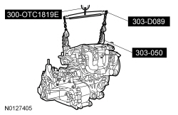
2,200# Floor Crane, Fold Away 300-OTC1819E or equivalent |

|
Lifting Bracket, Engine 303-050 (T70P-6000) |

|
Powertrain Lift 300-OTC1585AE or equivalent |

|
Spreader Bar 303-D089 (D93P-6001-A3) or equivalent |

|
Adjustable Grip Arm, 1735A 014-00001 or equivalent |
- With the vehicle in NEUTRAL, position it on a hoist. For additional information, refer to Section 100-02.
- Release the fuel system pressure. For additional information, refer to Section 310-00.
- Recover the A/C system. For additional information, refer to Section 412-00.
- Remove the Air Cleaner (ACL) and ACL outlet pipe. For additional information, refer to Section 303-12.
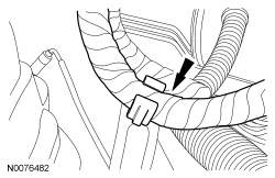
- Disconnect the crankcase vent tube from the valve cover.

- Remove the battery tray. For additional information, refer to Section 414-01.
- Disconnect the positive battery cable nut.
- Detach the 2 positive battery cable wire harness retainer.
- Remove the bolt and the negative battery cable ground.
- Disconnect the fuel tube quick connect coupling from the fuel rail and position the fuel tube aside. For additional information, refer to Section 310-00.
- Disconnect the Evaporative Emission (EVAP) tube and position aside. For additional information, refer to Section 310-00.
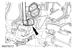
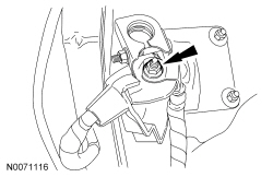
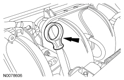
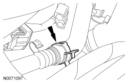
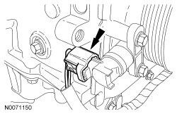
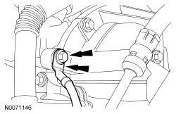
- Disconnect the power brake booster vacuum tube.
- Depress the quick connect locking ring.
- Pull the vacuum tube out of the quick connect fitting.
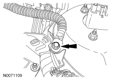
- Detach the brake booster vacuum hose retainer.
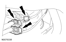
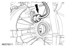
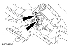
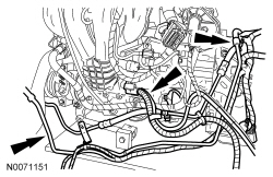
- Detach and disconnect the 2 engine harness electrical connectors.
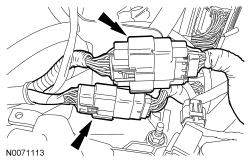
- Detach the engine harness from the coolant outlet bracket harness retainer.
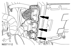
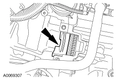
- Disconnect the 3 PCM electrical connectors.
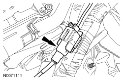
- Disconnect the starter wire harness electrical connector.
- Disconnect the Heated Oxygen Sensor (HO2S) and Catalyst Monitor Sensor (CMS) connectors and detach the wire harness retainer.
- Pressing the locking tab, disconnect the gearshift cables from the transaxle.
- Disconnect the shift cable from the shift mass.
- Disconnect the selector cable from the selector lever.
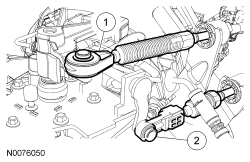
- Remove the gearshift levers from the bracket.
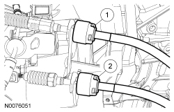
- Disconnect the shift cable from the retaining bracket by pulling the abutment sleeves rearward.
- Disconnect the selector cable from the retaining bracket by pulling the abutment sleeve rearward.
 WARNING: Carefully
read cautionary information on product label. For emergency medical information seek medical advice. In the USA or Canada on Ford/Motorcraft products call: 1-800-959-3673. For additional information, consult the product Material Safety Data Sheet (MSDS) if available. Failure to follow these instructions may result in serious personal injury.NOTICE: Do not spill brake fluid on painted or plastic surfaces or damage to the surface may occur. If brake fluid is spilled onto a painted or plastic surface, immediately wash the surface with water.
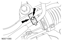
Remove the clip, then disconnect the clutch hydraulic line.
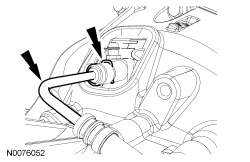
- Disconnect the hydraulic clutch line and grommet from the retaining bracket.
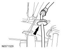
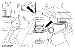
- Remove the engine oil level indicator.
- Remove the bolt and the radio capacitor ground cable.
- Remove the 2 front wheels and tires. For additional information, refer to Section 204-04.
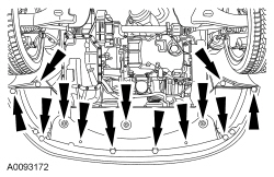
- Remove the retainers and the splash shield.
- Remove the accessory drive belt and tensioner. For additional information, refer to Section 303-05.
- Remove the generator. For additional information, refer to Section 414-00.
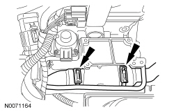
- Detach the 4 B+ battery cable wire harness retainers (2 shown) and position aside.
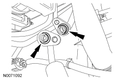
- Remove the 2 A/C tube nuts.
- Remove the nut and the A/C tube bracket from the A/C compressor stud bolt.
- Disconnect the A/C tubes from the compressor.
- Discard the 2 O-ring seals.
- Drain the engine cooling system. For additional information, refer to Section 303-03.
- Remove the cooling fan motor and shroud. For additional information, refer to Section 303-03.
- Disconnect the lower radiator hose from the radiator.

- Drain the engine oil.
- Install the drain plug and tighten to 28 Nm (21 lb-ft).
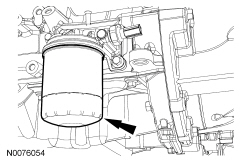
- Remove the engine oil filter and discard.
- Remove the LH halfshaft. For additional information, refer to Section 205-04.
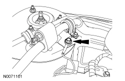
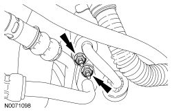
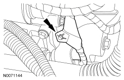
- Remove the bolt and the power steering tube clip.
- Remove the bolt and the power steering tubes from the steering gear.
- Discard the 2 power steering tube O-ring seals.
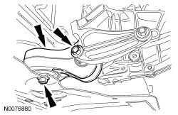
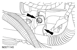
- Remove the 2 nuts and disconnect the flexpipe from the catalytic converter.
- Remove and discard the nuts and gasket.
- Remove the 2 catalytic converter support bracket-to-engine bolts.
- Remove the 2 bolts and the catalytic converter support bracket.
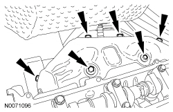
- NOTE:
Mark the location of bolts for installation.
Remove the 6 bolts and the catalytic converter heat shield.
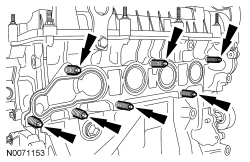
- Remove and discard the 7 catalytic converter-to-engine nuts.
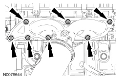
- Position aside the catalytic converter and support with mechanic's wire.
- Remove and discard the catalytic converter gasket.
- Remove the power steering pump. For additional information, refer to Section 211-02.
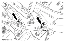
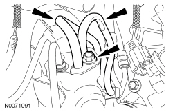
- Disconnect the upper radiator hose and the heater hose from the coolant bypass.
- Disconnect the heater hose from the coolant tube.
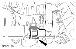
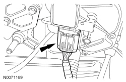
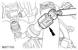
- Disconnect the throttle control electrical connector.
- NOTE:
The bolts are different lengths, mark the bolts for installation.
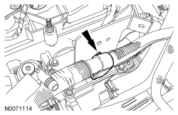
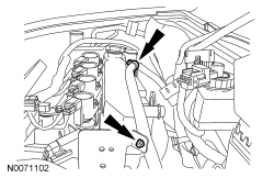
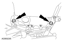
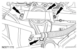
Remove the 2 bolts and the transaxle roll restrictor.
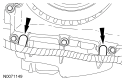
- Remove the 2 lower bellhousing-to-oil pan bolts.
- Remove the 2 oil pan-to-bellhousing bolts.
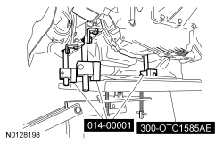
- Using the Powertrain Lift and Adjustable Grip Arm, fasten the engine to the lift table.
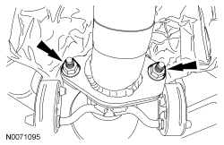
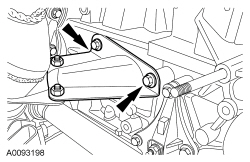
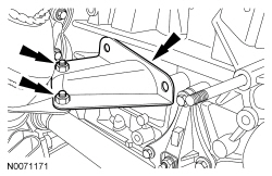
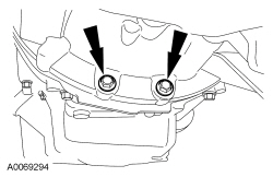
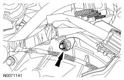
- Remove the 2 engine mount nuts.
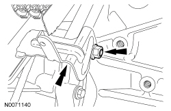
- Remove the 2 bolts, stud bolt and the engine mount.
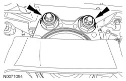
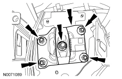
- Remove the 5 transaxle mount nuts and the transaxle mount plate.
- Lower the engine and transaxle assembly from the vehicle.
- Remove the nut for the HO2S and CMS wire connector bracket.
- Remove the nut and position the HO2S and CMS wire connector bracket aside.
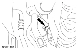
- Disconnect the Vehicle Speed Sensor (VSS) electrical connector.
- Disconnect the reversing lamp switch electrical connector.
- Disconnect the A/C compressor electrical connector.

- Disconnect the Power Steering Pressure (PSP) switch electrical connector.
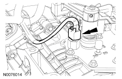
- Detach the 2 Crankshaft Position (CKP) sensor wire harness retainers.
- Disconnect the CKP sensor electrical connector.
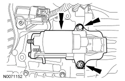
- Remove the 2 nuts and disconnect the starter motor electrical terminals.
- Detach the starter wire harness retainer from the starter motor stud bolt.
- Remove the nut from the starter motor stud bolt and remove the power steering tube bracket.
- Remove the bolt and the engine ground wire.
- Remove the 2 power steering tubes and the wiring harness as an assembly.
- Remove the bolt, stud bolt and the starter.
- Remove the starter isolator.
- Remove and discard the 7 catalytic converter manifold studs.
- NOTE:
Lower the engine to within a few inches of the floor.
Using the Floor Crane, Engine Lifting Bracket and Spreader Bar, remove the engine and transaxle assembly from the lift table.
- NOTE:
Mark the bolts and stud bolts location for installation.
Remove the 3 bellhousing-to-engine bolts, 2 stud bolts and separate the engine and transmission.
 Engine - Manual Transaxle - Engine - 2.0L - Installation
Special Tool(s)
2,200# Floor Crane, Fold Away
300-OTC1819E or equivalent
Lifting Bracket, Engine
303-050 (T70P-6000)
Powertrain ...
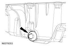
 Engine Oil Pressure (EOP) Switch - Engine - 2.0L - in Vehicle Repair
Material
Item
Specification
Motorcraft® Thread Sealant with PTFE
TA-24
WSK-M2G350-A2
Removal and Installation
With the vehicle in NEUTRAL, position it on a ...
More about Ford Focus:
Ford Focus Battery Disconnect
WARNING:
Batteries contain sulfuric acid and produce explosive gases. Work in a well-ventilated
area. Do not allow the battery to come in contact with flames, sparks or burning
substances. Avoid contact with skin, eyes or clothing. Shield eyes when working
near the battery to protect against ...
