Ford Focus Service Manual: Input Shaft

|
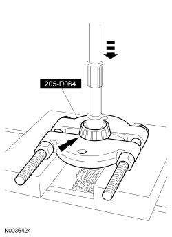
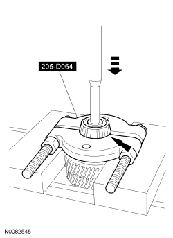
Remover, Bearing/Gear 205-D064 (D84L-1123-A) |
| Item | Specification |
|---|---|
| Motorcraft® Full Synthetic Manual Transmission Fluid XT-M5-QS | WSD-M2C200-C |
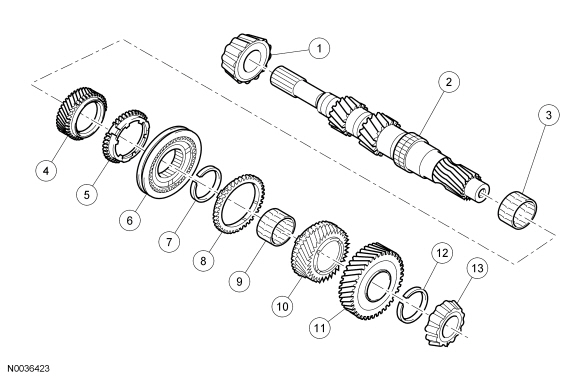
Input Shaft
| Item | Part Number | Description |
|---|---|---|
| 1 | 7025 | Input shaft bearing |
| 2 | 7017 | Input shaft |
| 3 | — | Third gear needle bearing |
| 4 | 7B340 | Third gear |
| 5 | 7107 | Third gear synchronizer ring |
| 6 | 7124 | Third/fourth gear synchronizer |
| 7 | — | Snap ring |
| 8 | 7107 | Fourth gear synchronizer ring |
| 9 | — | Fourth needle bearing |
| 10 | 7112 | Fourth gear |
| 11 | 7K316 | Fifth gear |
| 12 | — | Snap ring |
| 13 | 7025 | Input shaft bearing |
Disassembly
NOTE:
The inner synchronizer ring and the synchronizer cone must be handled very carefully.
NOTE:
If new components (bearings, shafts or the transaxle housings) are installed, the transaxle must be shimmed.
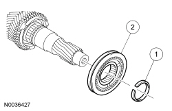
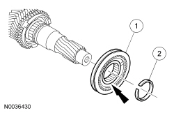
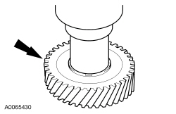
- NOTICE: The roller bearing will be damaged when it is removed from the
shaft. Do not reuse the bearing.
Position the input shaft on the press with the input shaft splines facing upward. Using the Bearing/Gear Remover, remove and discard the roller bearing.
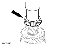
- NOTICE: The roller bearing will be damaged when it is removed from the
shaft. Do not reuse the bearing.
Reposition the input shaft with 5th gear end facing upward. Using a suitable press and the Bearing/Gear Remover, remove the roller bearing.
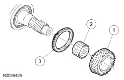
- Using a press and the Bearing/Gear Remover, remove and discard the snap ring then remove the 5th gear.
- Remove the 4th gear.
- Remove the 4th gear.
- Remove the 4th gear needle bearing.
- Remove the synchronizer ring.
- Check all components for wear or damage. Install new components as necessary.
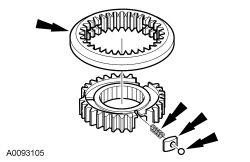
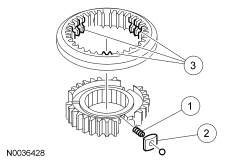
- Remove the 3rd/4th gear synchronizer assembly.
- Remove and discard the snap ring.
- Remove the 3rd/4th gear synchronizer assembly.
- Check the synchronizer for wear or damage. Install a new synchronizer as necessary.
- Disassemble the 3rd/4th gear synchronizer assembly. Take care when pulling the selector ring off the gear synchronizer hub. Remove the selector ring from the synchronizer hub. The detent balls are spring-loaded. Remove the compression springs, the blocker bars and the detent balls.
- Inspect the 3rd/4th synchronizer.
- Check for worn, nicked or broken teeth. Install a new synchronizer as necessary.
- Check keys for wear or distortion. Install a new synchronizer as necessary.
- Check springs for distortion. Install a new synchronizer as necessary.
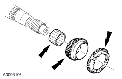
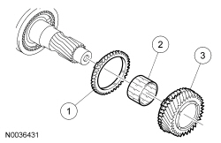
- Remove the synchronizer ring, 3rd gear and the 3rd needle gear bearing.
- Inspect the synchronizer ring, 3rd gear and the needle bearing for wear or damage. Install new components as necessary.
Assembly
- NOTE:
Using a press, install the gear wheels.
Carefully clean and check all sliding parts and lubricate them with clean manual transmission fluid before assembly.
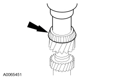
- Using a suitable tube and a press, install a new input shaft bearing (clutch housing bearing).
- Install the 3rd gear needle bearing, 3rd gear, gear wheel and the synchronizer ring.
- NOTE:
Place a rubber band around the synchronizer body. Install the springs, the synchronizer bars and detent balls. Slide the synchronizer sleeve over the body, while moving the rubber band downward.
Assemble the 3rd/4th gear synchronizer.
- Install the compression springs.
- Install the synchronizer bar and detent balls by pressing against the spring pressure.
- Align the selector ring with the hub and slide it on.
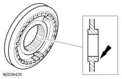
- NOTE:
Install the synchronizer hub with the large collar facing outward and the annular groove facing the small collar.
NOTE:
Install a new snap ring.
Install the 3rd/4th gear synchronizer assembly.- Install the synchronizer assembly.
- Install a new snap ring.
- Install the 4th gear.
- Install the synchronizer ring.
- Install the 4th gear needle bearing.
- Install the 4th gear.
- Using a suitable press, install 5th gear and a new snap ring.
- Using a suitable tube and a press, install a new input shaft bearing (transaxle housing bearing).
 External Controls
The manual transaxle external controls consists of the following:
Gearshift cables
shift cable
selector cable
Gearshift lever
Gearshift lever knob and boot
The man ...
 Manual Transaxle/Transmission - MTX75
The MTX-75 manual transaxle features the following:
Two-part aluminum housing
The input shaft has 2 tapered roller bearings. Input shaft end play is controlled
by a selective shim located u ...
More about Ford Focus:
Ford Focus Range Selection
The transaxle range selector has 5 positions: P, R, N, D, L.
Park
In selector lever position P, no gear is selected. The parking pawl is engaged
manually by the selector lever cable and the manual control lever shaft.
For safety reasons, always apply the parking brake whenever the vehicle ...
