Ford Focus Service Manual: Transaxle

|
Alignment Tool, Transmission Range Sensor 307-415 |

|
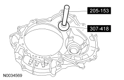
Handle 205-153 (T80T-4000-W) |

|
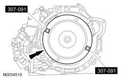
Handle, Torque Converter 307-091 (T81P-7902-C) |

|
Holding Tool, Final Drive Input Gear 307-413 |

|
Installer, Axle Oil Seal 205-259 (T87P-3254-A) |

|
Installer, Differential Bearing Cup 205-118 (T77F-4222-A) |

|
Installer, Differential Fluid Seal 307-256 (T92P-77000-FH) |

|
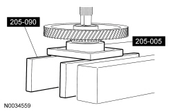
Installer, Drive Pinion Bearing Cone 205-005 (T53T-4621-C) |

|
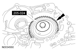
Installer, Drive Pinion Bearing Cup 205-024 (T67P-4616-A) |

|
Installer, Output Shaft Seal 307-572 |

|
Installer, Transfer Gear Bearing Cup 307-418 |

|
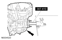
Mounting Bracket, Transmission 307-410 |

|
Plate, Bearing/Oil Seal 205-090 (T75L-1165B) |

|
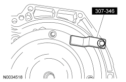
Retainer, Torque Converter 307-346 (T97T-7902-A) |

|
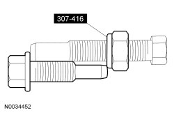
Select Gauge, Transmission Band 307-416 |

|
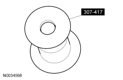
Shim Gauge, Differential/Transfer Gear Bearing 307-417 |

|
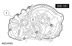
Shim Selection Set 308-161 (T88C-77000-C) |

|
Shim Selection Set 308-164 (T88C-77000-JF) |

|
Socket, Final Drive Input Nut 307-414 |

|
Wrench Guide Plate 307-420 |
| Item | Specification |
|---|---|
| Motorcraft® MERCON® LV Automatic Transmission Fluid XT-10-QLVC (US); CXT-10-LV12 (Canada) | MERCON® LV |
| Thread Sealant with PTFE TA-24 | WSK-M2G350-A2 |
| Threadlock and Sealer TA-25 | WSK-M2G351-A5 |
| Ultra Silicone Sealant TA-29 | — |
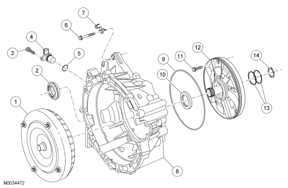
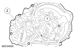
Converter Housing with Converter Assembly and Pump Assembly
| Item | Part Number | Description |
|---|---|---|
| 1 | 7902 | Converter assembly |
| 2 | 1177 | Seal assembly — differential |
| 3 | — | Output Shaft Speed (OSS) sensor bolt |
| 4 | 7H103 | OSS sensor |
| 5 | W706315-S300 | O-ring — OSS sensor |
| 6 | — | Bolt — converter housing |
| 7 | — | Retainer — fluid tube |
| 8 | 7005 | Converter housing |
| 9 | 7A248 | Seal — pump |
| 10 | 7A248 | Seal assembly — pump |
| 11 | — | Bolt — pump |
| 12 | 7A103 | Pump assembly |
| 13 | 7D019 | Seals — forward clutch cylinder |
| 14 | 7H042 | Washer — pump support thrust |
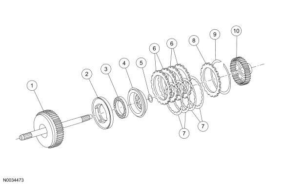
Forward Clutch
| Item | Part Number | Description |
|---|---|---|
| 1 | 7F207 | Shaft assembly — turbine |
| 2 | 7A262 | Piston assembly — forward clutch |
| 3 | 7F235 | Spring assembly — forward piston return |
| 4 | 7H360 | Piston — forward clutch balance |
| 5 | 7H365 | Snap ring — forward clutch balance piston |
| 6 | 7B442 | Steel plates — forward clutch separator (4 required) |
| 7 | 7B164 | Friction plate assembly — forward clutch (4 required) |
| 8 | 7B066 | Plate — forward/direct clutch pressure (1 each) |
| 9 | 7D483 | Retaining ring (selective) |
| 10 | 7B067 | Hub — forward clutch cylinder |
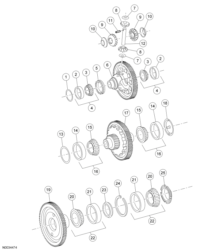
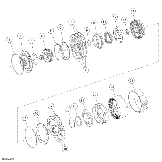
Differential Assembly and Final Drive Input
| Item | Part Number | Description |
|---|---|---|
| 1 | 4067 | Shim — differential bearing |
| 2 | 4222 | Cups — differential bearing |
| 3 | 4221 | Cone and roller assemblies |
| 4 | 4221 | Bearing assemblies |
| 5 | 7H150 | Wheel — Output Shaft Speed (OSS) sensor |
| 6 | 7F465 | Differential and gear assembly — transaxle |
| 7 | 4230 | Pinion thrust washers (2 required) |
| 8 | 4215 | Differential pinion gears (2 required) |
| 9 | 4236 | Differential side gears (2 required) |
| 10 | 4228 | Side gear thrust washers (2 required) |
| 11 | 4241 | Pin |
| 12 | 4211 | Differential pinion shaft |
| 13 | 7H367 | Shim — transfer shaft roller bearing |
| 14 | 7H344 | Cups — transfer shaft roller |
| 15 | 7170 | Cone and roller assemblies |
| 16 | 7H338 | Bearing assemblies — transfer shaft (2 required) |
| 17 | 7H348 | Transfer shaft gear assembly |
| 18 | 7L267 | Funnel — transfer shaft |
| 19 | 7F342 | Gear — final drive input |
| 20 | 7M102 | Cone and roller assemblies |
| 21 | 7C236 | Bearing cups |
| 22 | 7F403 | Bearing assemblies (2 required) |
| 23 | 7H369 | Spacer |
| 24 | 7H106 | Retainer ring |
| 25 | 7B364 | Nut |
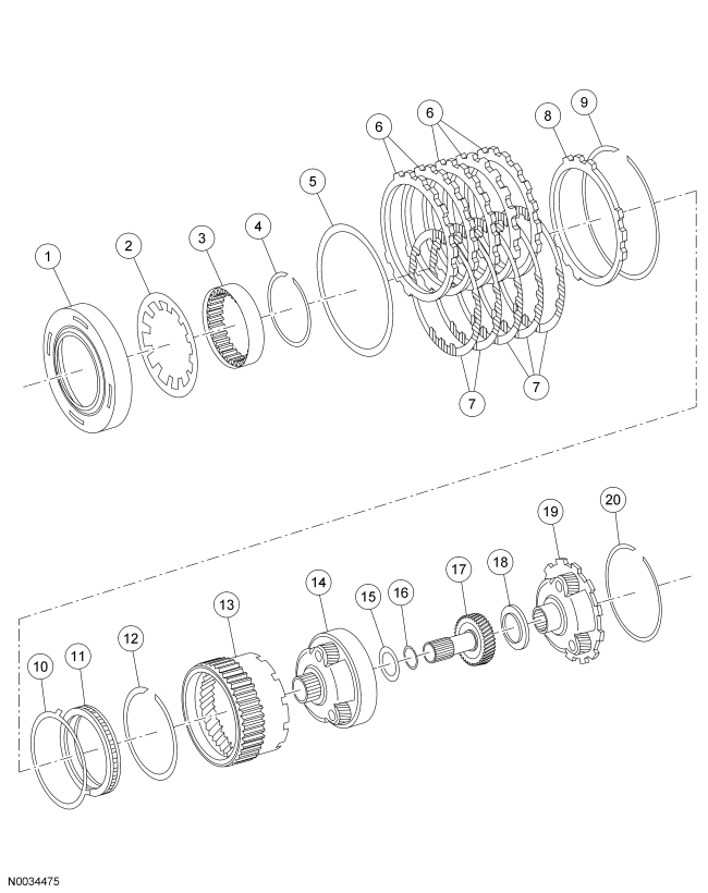
Clutches and Planet Gears
| Item | Part Number | Description |
|---|---|---|
| 1 | 7A262 | Piston — low/reverse clutch |
| 2 | 7B070 | Spring — low/reverse clutch return |
| 3 | 7D171 | Race — low One-Way Clutch (OWC) — inner |
| 4 | 7D483 | Retaining ring — low OWC |
| 5 | 7B070 | Spring — low/reverse clutch wave |
| 6 | 7B442 | Steel plates — low/reverse clutch separator (5 required) |
| 7 | 7B164 | Friction plate assembly — low/reverse clutch (5 required) |
| 8 | 7B066 | Pressure plate — low/reverse clutch |
| 9 | 7D483 | Retaining ring — low/reverse clutch plate (selective) |
| 10 | 7H199 | Retainer — low gear OWC |
| 11 | 7A089 | OWC assembly — low |
| 12 | 7D483 | Retaining ring |
| 13 | 7D392 | Front ring gear |
| 14 | 7A398 | Gear assembly — front planet |
| 15 | 7H375 | Bearing assembly — front planet carrier thrust |
| 16 | 7H362 | Snap ring |
| 17 | 7A399 | Front planet sun gear assembly |
| 18 | 7H337 | Bearing assembly — front sun gear thrust |
| 19 | 7D006 | Gear assembly — rear planet |
| 20 | 7H361 | Snap ring |
Clutches and Band
| Item | Part Number | Description |
|---|---|---|
| 1 | 7D483 | Retaining ring — reverse clutch |
| 2 | 7A019 | Rear sun gear assembly |
| 3 | 7C041 | Thrust bearing assembly — rear sun gear |
| 4 | 7H351 | Direct clutch hub assembly |
| 5 | 7D483 | Retaining ring |
| 6 | 7B066 | Pressure plate — forward/direct clutch (1 each) |
| 7 | 7B164 | Friction plate assembly — forward/direct clutch (forward 4, direct 3) |
| 8 | 7B442 | Steel plates — direct clutch (3 required) |
| 9 | 7H363 | Snap ring — direct clutch balanced piston |
| 10 | 7H359 | Direct clutch balanced piston |
| 11 | 7F235 | Piston return spring assembly — forward/direct clutch |
| 12 | 7A262 | Piston assembly — direct clutch |
| 13 | 7H335 | Thrust bearing assembly — direct clutch |
| 14 | 7F283 | Cylinder assembly — direct clutch |
| 15 | 7D483 | Retaining ring — reverse clutch (selective) |
| 16 | 7B066 | Pressure plate — reverse clutch |
| 17 | 7B442 | Steel plates — reverse clutch (2 required) |
| 18 | 7B164 | Friction plate assembly — reverse clutch (2 required) |
| 19 | 7H075 | Spring retainer ring — reverse clutch |
| 20 | 7D406 | Spring retainer — reverse clutch |
| 21 | 7B070 | Piston return spring — reverse clutch |
| 22 | 7D402 | Piston assembly — reverse clutch |
| 23 | 7D044 | Drum assembly — intermediate and overdrive |
| 24 | 7D034 | Band assembly — intermediate and overdrive |
Main Control Assembly
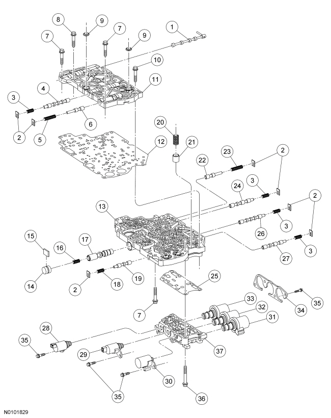
| Item | Part Number | Description |
|---|---|---|
| 1 | 7D142 | Valve assembly — manual control |
| 2 | 7F194 | Plates — spring retainer (7 required) |
| 3 | 7H140 | Springs — bypass clutch control (4 required) |
| 4 | 7G179 | Valve — bypass clutch control |
| 5 | 7K720 | Spring — modulation valve |
| 6 | 7G408 | Valve — line pressure modulator |
| 7 | W500100 | Bolts M6 x 30 (3 required) |
| 8 | W705271 | Bolt M6 x 63 (5 required) |
| 9 | 7N266 | Seals — valve body |
| 10 | W705271 | Bolt M6 x 60 (5 required) |
| 11 | 7A092 | Body — control valve upper |
| 12 | 7Z490 | Separator plate and gasket assembly |
| 13 | 7A101 | Body — control valve lower |
| 14 | 7R294 | Stop — main regulator valve |
| 15 | 7F445 | Clip — throttle valve plunger sleeve |
| 16 | 7A270 | Spring — main fluid pressure regulator valve |
| 17 | 7C338 | Valve — main fluid pressure regulator |
| 18 | 7G411 | Spring — solenoid regulator valve |
| 19 | 7H392 | Valve — shift solenoid |
| 20 | 7D400 | Spring — intermediate servo accumulator |
| 21 | 7D398 | Piston — intermediate servo accumulator |
| 22 | 7G408 | Valve — converter pressure relief |
| 23 | 7G316 | Spring — converter regulator valve |
| 24 | 7M040 | Valve — lock-up control |
| 25 | 7Z490 | Gasket — solenoid body |
| 26 | 7G179 | Valve — low/reverse shift |
| 27 | 7M040 | Valve — 3-4 shift |
| 28 | 7H148 | Shift Solenoid B (SSB) (on/off) valve |
| 29 | 7H148 | Shift Solenoid A (SSA) (on/off) valve |
| 30 | 7G383 | Line Pressure Control (LPC) |
| 31 | 7G484 | Pulse-Width Modulation (PWM) solenoid valve Shift Solenoid C (SSC) |
| 32 | 7G484 | PWM solenoid valve Shift Solenoid E (SSE) |
| 33 | 7G484 | PWM solenoid valve Shift Solenoid D (SSD) |
| 34 | 7H185 | Bracket — shift control solenoid hold down |
| 35 | W500211 | Screws M6 x 12 (7 required) |
| 36 | W500012 | Screw M6 x 14 (2 required) |
| 37 | 7G391 | Body — solenoid shift throttle pressure |
Case Assembly
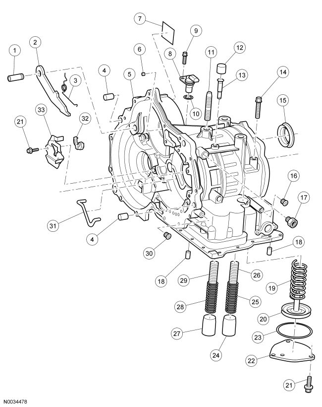
| Item | Part Number | Description |
|---|---|---|
| 1 | 7D071 | Parking pawl shaft |
| 2 | 7A441 | Parking brake pawl |
| 3 | 7D070 | Pawl return spring |
| 4 | W706892-S300 | Case dowels |
| 5 | 7005 | Case |
| 6 | 7H389 | Case orifice plug |
| 7 | 7B148 | Service identification tag |
| 8 | 7M101 | Turbine Shaft Speed (TSS) sensor |
| 9 | W500214-S300 | Bolt M6-1 x 20 |
| 10 | W706316-S300 | O-ring |
| 11 | W703961-S309 | Case stud |
| 12 | 7L282 | Rubber vent cap |
| 13 | 7A246 | Breather tube |
| 14 | 7F206 | Overdrive (O/D) band anchor stud |
| 15 | 1177 | Differential seal |
| 16 | — | 1/8-27 Hex socket |
| 17 | — | Connector 1/4 x 5/8 x 22.9 |
| 18 | 7B362 | Case dowel pins |
| 19 | 7D028 | Servo piston return spring |
| 20 | 7D021 | Intermediate and overdrive servo piston and seal assembly |
| 21 | W500214-S300 | Screws M6-1 x 20 |
| 22 | 7D027 | Intermediate O/D band servo cover |
| 23 | 7D024 | Intermediate O/D servo cover seal |
| 24 | 7F251 | Neutral/drive accumulator piston |
| 25 | 7G300 | Neutral/drive shift accumulator outer spring |
| 26 | 7G395 | Neutral/drive shift accumulator inner spring |
| 27 | 7F251 | 1-2 shift accumulator piston |
| 28 | 7G267 | 1-2 shift accumulator outer spring |
| 29 | 7G326 | 1-2 shift accumulator inner spring |
| 30 | W701515-S309 | Line tap plug |
| 31 | 7N148 | Oil transfer tube |
| 32 | 7G101 | Park pawl actuating abutment |
| 33 | 7D419 | Park pawl actuating plate |
Snap Rings
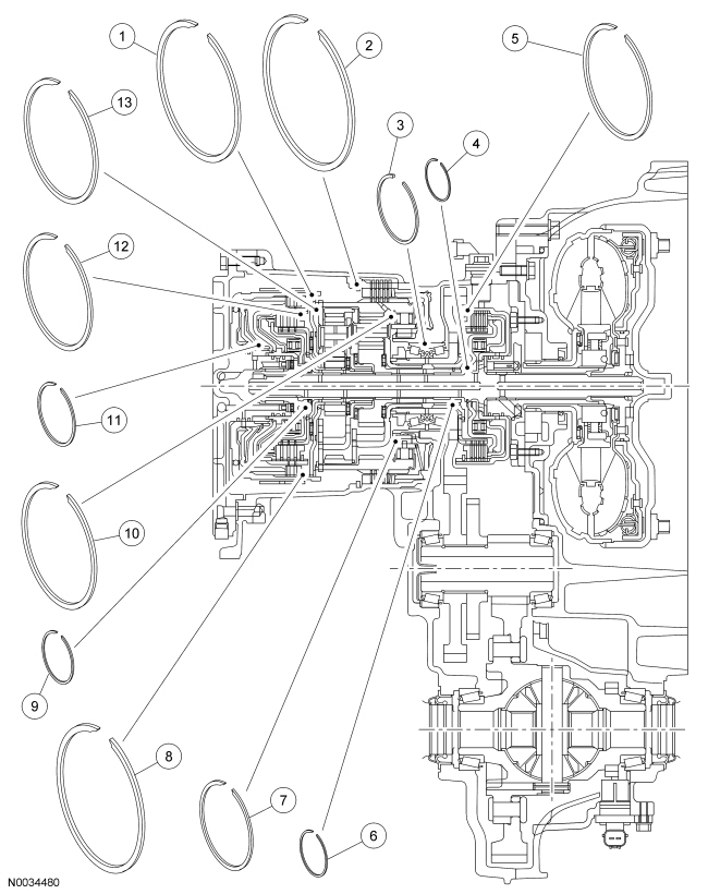
| Item | Part Number | Description |
|---|---|---|
| 1 | 7D483 | Ring — reverse clutch retaining |
| 2 | 7D483 | Ring — low/reverse clutch plate retaining (select fit) |
| 3 | 7H106 | Ring — final drive retainer |
| 4 | 7H365 | Ring — forward clutch balance piston |
| 5 | 7D483 | Ring — forward/direct clutch plate retaining (select fit) |
| 6 | 7D483 | Snap ring — front sun gear |
| 7 | 7D483 | Ring — low One-Way Clutch (OWC) retaining |
| 8 | 7D483 | Ring — reverse clutch retaining (select fit) |
| 9 | 7H363 | Snap ring — direct clutch balance piston |
| 10 | 7D483 | Ring — forward/direct clutch planet retaining |
| 11 | 7H075 | Ring — reverse clutch spring retaining |
| 12 | 7D483 | Ring — forward/direct clutch plate retaining (select fit) |
| 13 | 7H361 | Snap ring — rear planet assembly |
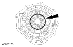
Assembly
- Using the Drive Pinion Bearing Cone Installer, install the final drive input
gear bearing.
- Install the final drive input gear bearing.
- Install the Drive Pinion Bearing Cone Installer.
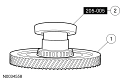
- Using an arbor press, the Bearing/Oil Seal Plate and the Drive Pinion Bearing Cone Installer, seat the final drive input gear bearing.
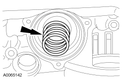
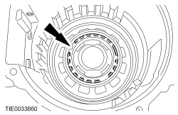
- Install a new collapsible spacer.
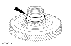
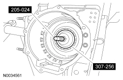
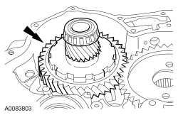
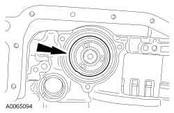
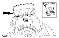
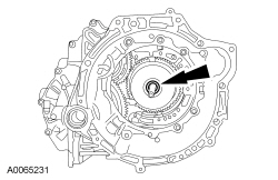
- Using the Drive Pinion Bearing Cup Installer, position the final drive input gear.
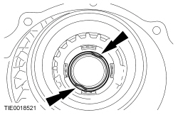
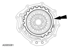
- NOTICE: Hold the final drive input gear while installing the final drive
input gear bearing to prevent it from falling out of the transaxle case or damage
to the input gear can occur.
Rotate the transaxle 180 degrees.
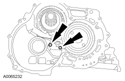
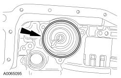
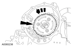
- Using the Drive Pinion Bearing Cup Installer and Differential Fluid Seal Installer, install the final drive input gear bearing.
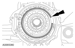
- Rotate the transaxle 180 degrees.
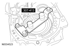
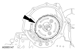
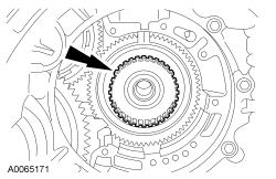
- Using the Final Drive Input Gear Holding Tool, lock the final drive input gear.
- Rotate the transaxle 180 degrees.
- NOTE:
A high tightening torque of approximately 200 Nm (148 lb-ft) is necessary to crush the collapsible spacer for correct bearing preload.
NOTE:
If the preload is too high, a new collapsible spacer must be installed.
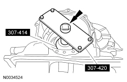
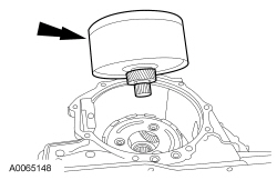
Using the Wrench Guide Plate and Final Drive Input Nut Socket, tighten the nut in small increments to achieve a turning torque of 0.55-0.85 Nm (4.9-7.5 lb-in).
- Rotate the transaxle 180 degrees.
- NOTE:
Make sure that the final drive rotates.
Unlock the Final Drive Input Gear Holding Tool.
- Rotate the transaxle 180 degrees.
- NOTICE: Make sure the bearing preload is between 0.55-0.85 Nm (4.9-7.5
lb-in) or bearing failure can occur.
NOTE:
Rotate the gear 10 times to make sure that the bearings are correctly seated.
Using the Wrench Guide Plate and Final Drive Input Nut Socket, measure the rotating torque.- Rotational torque is 0.55-0.85 Nm (4.9-7.5 lb-in).
- After achieving the correct rotating torque specification, remove the Wrench Guide Plate and Final Drive Input Nut Socket and stake the nut to prevent movement.
- Rotate the transaxle 180 degrees.
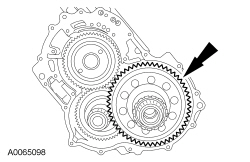
- Position the transfer shaft gears in the transaxle case.
- Install the parking pawl return spring.
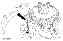
- Connect the spring.
- Install the parking pawl abutment.
- Install the lever.
- Install the pin.
- Connect the spring.
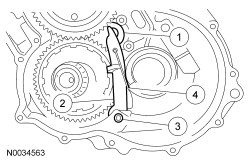
- Install the parking pawl assembly cover and bolts.
- Tighten to 13 Nm (115 lb-in).
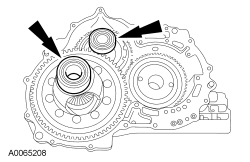
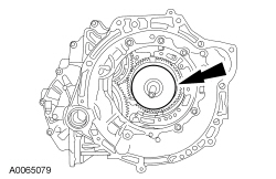
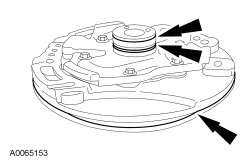
- Install the differential case assembly.
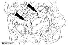
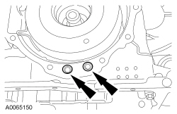
- Position the bearing cups.
- Install the Differential/Transfer Gear Bearing Shim Gauge and Shim Selection Set.
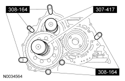
- NOTICE: Do not use the bolts from Shim Selection Set 308-164, they will
not work. Use only the bolts from Shim Selection Set 308-161 or damage to the
transaxle case threads can occur.
NOTE:
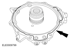
The converter housing cover must be installed evenly or an incorrect reading will result.
Using the Shim Selection Set, assemble the transaxle for end play measurement.- Position the converter housing.
- Install the Shim Selection bolts and seat the case cover flat.
- Tighten to 5 Nm (44 lb-in).
- Remove the converter housing.
- Remove bolts.
- Remove the converter housing.
- Remove the Differential/Transfer Gear Bearing Shim Gauge and Shim Selection Set.
- Remove the bearing cups.
- NOTE:
If the plunger is above the contact surface, the reading will be incorrect.
To determine the correct transfer shaft shim, measure the depth of the plunger on the Differential/Transfer Gear Bearing Shim Gauge and select the correct transfer shaft shim. For additional information, refer to Specifications in this section.
- NOTE:
If the plunger is above the contact surface, the reading will be incorrect.
To determine the correct differential shaft shim, measure the depth of the plunger on the Differential/Transfer Gear Bearing Shim Gauge and select the correct differential shaft shim. For additional information, refer to Specifications in this section.
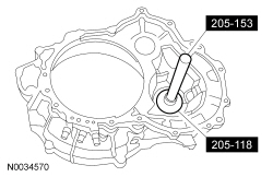
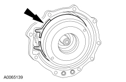
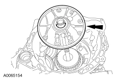
- Using the Transfer Gear Bearing Cup Installer and Handle, install the correct transfer shaft shim and bearing cup into the converter housing.
- Using the Differential Bearing Cup Installer and Handle, install the correct differential shaft shim and differential case bearing cup into the converter housing.
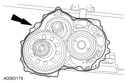
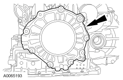
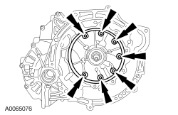
- Apply a 1 mm (0.039 in) thick bead of silicone sealer to the case half.
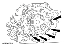
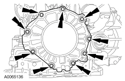
- NOTICE: Failure to apply threadlock and sealer to the bolts can result
in a transmission fluid leak.
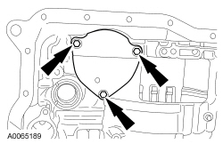
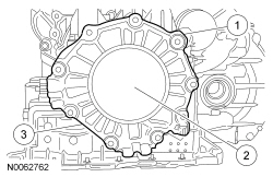
Position the converter housing on the transaxle case. Apply threadlock and sealer to the 5 bolts. Install and hand-tighten the bolts in the transaxle case.
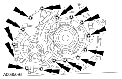
- Install the rest of the converter housing-to-transaxle case bolts and tighten
all of the bolts.
- Tighten to 22 Nm (16 lb-ft).
- Install the intermediate/overdrive band servo piston return spring.
- Install the intermediate/overdrive servo piston.
- Install the O-ring seal.
- NOTE:
The 3 bolts must be loosely installed, then tightened in a crisscross sequence to compress the intermediate/overdrive spring evenly.
Install the intermediate/overdrive band servo cover and bolts.
- Tighten to 13 Nm (115 lb-in).
- Install the park pawl assembly and bolt.
- Tighten to 13 Nm (115 lb-in).
- NOTE:
Lubricate the O-ring with transmission fluid prior to assembly.
Install the new O-rings on the manual control lever shaft.
- Install the manual control lever shaft.
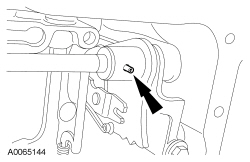
- NOTE:
The roll pin does not need to sit flush with the park pawl assembly.
Install a new manual control lever shaft roll pin.
- Loosely install the Transmission Range (TR) sensor.
- NOTE:
The neutral drive accumulator springs are thinner than the 1-2 accumulator springs.
Install the thinner and longer neutral drive accumulator springs.
- Install the neutral drive accumulator piston.
- Install the 1-2 accumulator springs.
- Install the 1-2 accumulator piston.
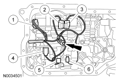
- Inspect the seals. Lubricate the seals in transmission fluid. Install the transaxle internal harness electrical connector.
- NOTE:
Make sure that the manual valve is in the manual control valve selector lever.
NOTE:
Do not fully tighten the bolts at this stage.
Install the main control valve body.
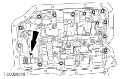
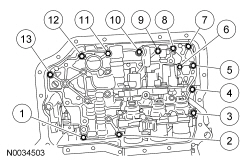
- Tighten the main control valve body bolts.
- Tighten the bolts in the sequence shown.
- Tighten to 9 Nm (80 lb-in).
- Tighten the bolts in the sequence shown.
- NOTE:
It is necessary to connect the connectors in the same positions as noted in disassembly. Connector color letters are cast in the solenoid body.
Install the main control wiring harness, connect the electrical connectors and install the main control ground wire bolt.
- Shift Solenoid C (SSC) , color N (White)
- Shift Solenoid E (SSE) , color G (Green)
- Shift Solenoid D (SSD) , color L (Blue)
- Line Pressure Control (LPC) , color B (Black)
- Shift Solenoid A (SSA) , color N (Natural)
- Shift Solenoid B (SSB) , color B (Black)
- Tighten the main control ground wire bolt to 10 Nm (89 lb-in).
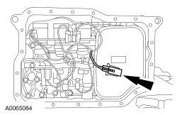
- Install the transmission fluid filter.
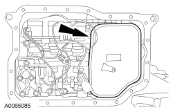
- Connect the Transmission Fluid Temperature (TFT) sensor.
- NOTE:
Do not use more than the specified amount of sealer on the transmission fluid pan or internal transaxle damage could occur.
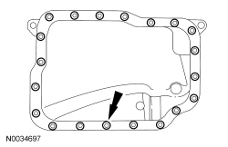
Apply a bead 1.5 mm (0.059 in) diameter of silicone sealer to the transmission fluid pan.
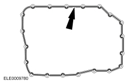
- Install the transmission fluid pan.
- Tighten to 10 Nm (89 lb-in).
- Rotate the transaxle 180 degrees.
- Install the low/reverse clutch piston.
- NOTE:
Be sure the low/reverse clutch return spring is installed so that the tabs are facing up.
Install the low/reverse clutch return spring.
- Install the wave spring.
- Install the low One-Way Clutch (OWC) inner race.
- NOTE:
The opening of the retaining ring must be at the 10 o'clock position.
Install the low OWC retaining ring.
- Install the low/reverse plates and pressure plate.
- Install the low reverse clutch plate selective retaining ring.
- Using a feeler gauge, measure the clutch clearance.
- Compare the low reverse clutch pack clearance to the specification (2.2-2.5 mm [0.0866-0.0984 in]). If the clutch pack clearance is not within specification, select and install the correct size selective retaining ring to obtain the specified clearance.
- NOTE:
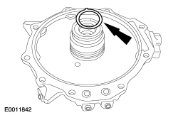
Make sure that the snap ring is installed before installing the planet assembly.
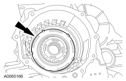
Install the planet assembly.
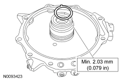
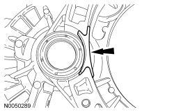
- NOTICE: If the planet assembly is installed correctly, the edge of the
planet assembly will fit flush with the transaxle case. If the planet assembly
does not fit flush with the transaxle case, further assembly will cause damage
to the transaxle.
Inspect the planet assembly installation.
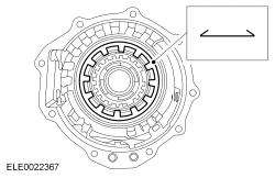
- NOTE:
The planet assembly must only rotate counterclockwise. If the planet assembly rotates clockwise, then the OWC was not installed correctly.
Check to make sure that the OWC is correctly installed.
- Rotate the planet assembly clockwise and counterclockwise.
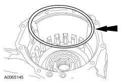
- Install the intermediate/Overdrive (O/D) drum assembly.
- Install the intermediate/O/D band.
- Install the direct clutch cylinder thrust bearing with the rollers facing up.
- Install new end cover-to-case seals.
- Install new end cover seals.
- Install the direct clutch hub bearing shim and an additional shim to increase the total shim thickness to specification shown or greater.
- NOTICE: Failure to support the transaxle end cover in the center can
result in inaccurate measurements causing damage to the transaxle.
Measure the gap between the transaxle end cover and the transaxle assembly.
- Position the transaxle end cover on the transaxle assembly.
- Support the transaxle end cover in the center.
- Measure the gap between the transaxle end cover and the transaxle assembly.
- Remove the transaxle end cover.
- NOTE:
The clearance for the direct clutch bearing shim is 0.25-0.50 mm (0.009-0.019 in).
NOTE:
The correct shim thickness is between minimum and maximum.
Choose and install the correct direct clutch hub bearing shim:- Line 1: total amount of shim thickness used during transaxle end cover mock up.
- Line 2: measure the gap between transaxle end cover and transaxle case.
- Line 3: subtract Line 2 from Line 1 to obtain the actual clearance.
- Line 4: subtract 0.25 mm (0.009 in) from Line 3 for maximum shim thickness.
- Subtract 0.50 mm (0.019 in) from Line 3 for the minimum thickness shim.
- NOTICE: Applying too much silicone sealer in the area of the fluid return
holes may cause the fluid return holes to become blocked and cause a transmission
failure.
Apply a 1 mm (0.039 in) bead of silicone sealer to the transaxle end cover.
- Install the transaxle end cover.
- Tighten to 22 Nm (16 lb-ft).
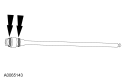
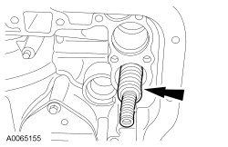
- Using the Transmission Band Select Gauge, collapse the intermediate/O/D
band.
- Tighten to 5 Nm (44 lb-in), then back out three and a half turns.
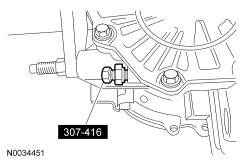
- Holding the Transmission Band Select Gauge, lightly seat the nut against the transaxle case, then remove the Transmission Band Select Gauge without changing the relationship of the nut on the bolt.
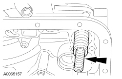
- Using the Transmission Band Select Gauge, select an intermediate/O/D band bolt that measures from the end of the bolt to the face of the nut as shown.
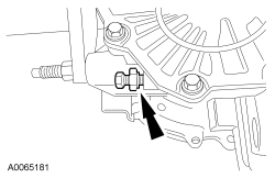
- NOTE:
Apply thread sealer to the bolt.
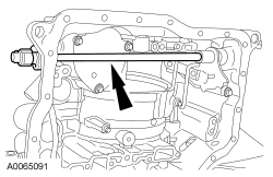
Install the intermediate/O/D band anchor bolt.
- Tighten to 45 Nm (33 lb-ft).
- Rotate the transaxle 180 degrees.
- Install the forward clutch hub.
- Install the forward clutch assembly.
- Install the forward clutch thrust washer.
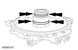
- Install new pump seals and lubricate with clean transmission fluid.
- Install the pump (do not force the pump down at this time).
- NOTICE: Failure to apply threadlock and sealer to the bolts can result
in a transmission fluid leak.
Apply threadlock and sealer to the bolts and install the pump-to-case bolts.
- Use the bolts to seat the pump.
- Tighten the bolts in a crisscross pattern.
- Tighten to 30 Nm (22 lb-ft).
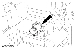
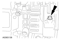
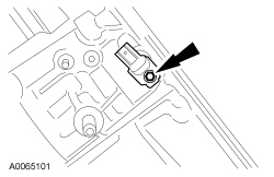
- Install the Output Shaft Speed (OSS) sensor.
- Tighten to 10 Nm (89 lb-in).
- NOTE:
Apply thread sealer to the bolt.
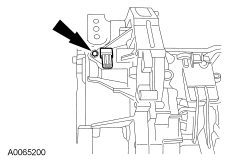
Install the Turbine Shaft Speed (TSS) sensor.
- Tighten to 10 Nm (89 lb-in).
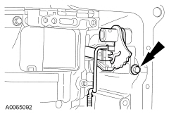
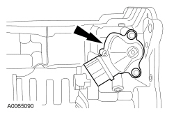
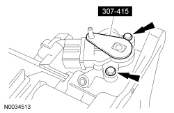
- Using the Transmission Range Sensor Alignment Tool, align the TR sensor
and tighten the bolts.
- Tighten to 10 Nm (89 lb-in).
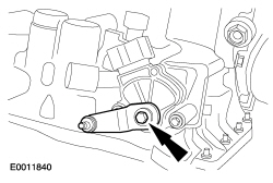
- NOTICE: Do not use air tools on this bolt. Hold the manual control lever
while tightening the manual control lever bolt. Damage to the manual control
lever shaft will occur.
Install the manual control lever bolt.
- Tighten to 30 Nm (22 lb-ft).
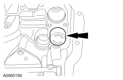
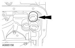
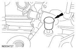
- Install the vent cap past the second detent notch. Be sure the vent moves up and down freely.
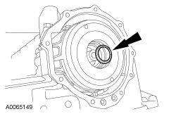
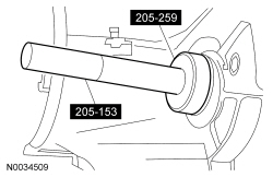
- Using the Axle Oil Seal Installer and Handle, install the LH halfshaft seal.
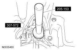
- Using the Output Shaft Seal Installer and Handle, install the RH halfshaft seal.
- Install the differential opening cover.
- Using the Torque Converter Handles, install the torque converter.
- Using the Torque Converter Retainer, secure the torque converter.
- Remove the Transmission Mounting Bracket from the transaxle.
 Servo Bore Repair
NOTE: The 4F27 Servo Bore Master Repair Kit NRL4F27 should be used
to repair a transmission case with 2-4 band servo pin bore wear. The use of this
kit will repair the 2-4 band servo pin bore back ...
 Transaxle Case
Special Tool(s)
Handle
205-153 (T80T-4000-W)
Installer, Axle Oil Seal
205-259 (T87P-3254-A)
Installer, Differential Bearing Cup ...
More about Ford Focus:
Ford Focus Child seats
WARNINGS:
Secure children that are less than
150 centimetres tall or less than 12
years of age in a suitable, approved
child restraint, in the rear seat.
Original text according to ECE
R94.01: Extreme Hazard! Do not use
a rearward facing child restraint on
a seat protected by an air ba ...
