Ford Focus Service Manual: All engines Assembly
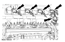
- NOTE:
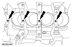
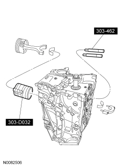
If the oil squirters are being reused, they must be installed in the same location as marked during disassembly.
NOTE:
The front bulkhead does not have an oil squirter.
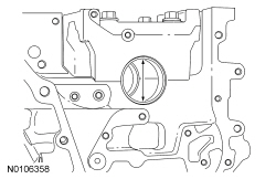
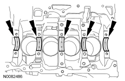
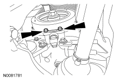
Install the 4 oil squirters.- Tighten to 4 Nm (35 lb-in).
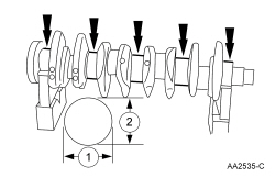
- Measure each of the crankshaft main bearing journal diameters in at least 2 directions and record the smallest diameter for each journal.
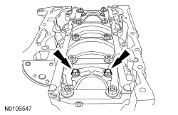
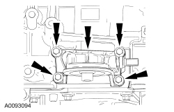
- Position the main bearing beam in the engine block with the main bearing beam mounted flush with the rear face of the engine block.
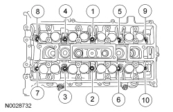
- Using the original main bearing beam bolts, install and tighten the 10 main
bearing beam bolts.
- Tighten the bolts in the sequence shown in 3 stages.
- Stage 1: Tighten to 5 Nm (44 lb-in).
- Stage 2: Tighten to 25 Nm (18 lb-ft).
- Stage 3: Tighten an additional 90 degrees.
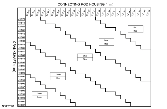
- Measure each crankshaft block housing main bearing bore diameter.
- Remove the bolts and the main bearing beam.
- Discard the main bearing beam bolts.
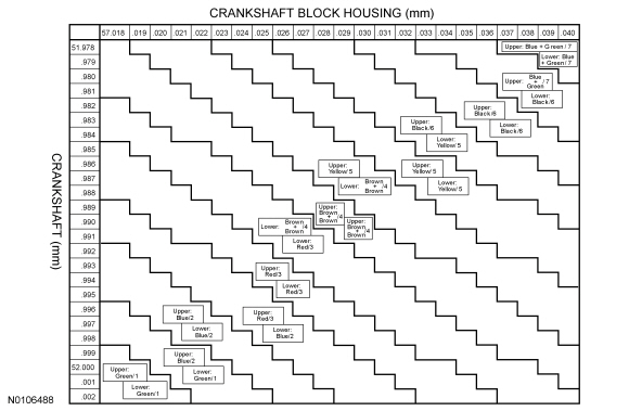
- Using the chart, select the crankshaft main bearings.
- NOTICE: The rod cap installation must keep the same orientation as marked
during disassembly or engine damage may occur.
Using the original connecting rod cap bolts, install the connecting caps and bolts.
- Tighten the bolts in 2 stages.
- Stage 1: Tighten to 29 Nm (21 lb-ft).
- Stage 2: Tighten an additional 90 degrees.
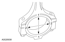
- Measure the connecting rod large end bore in 2 directions. Record the smallest
measurement for each connecting rod.
- Remove the bolts and the connecting rod cap.
- Discard the connecting rod cap bolts.
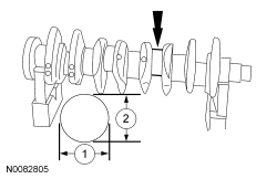
- Measure each of the crankshaft connecting rod bearing journal diameters in at least 2 directions. Record the smallest measurement for each connecting rod journal.
- Using the chart, select the correct connecting rod bearings for each crankshaft connecting rod journal.
- NOTE:
Before assembling the cylinder block, all sealing surfaces must be free of chips, dirt, paint and foreign material. Also, make sure the coolant and oil passages are clear.
NOTE:
If reusing the crankshaft main bearings, install them in their original positions and orientation as noted during disassembly.
NOTE:
The center bulkhead is the thrust bearing.
Lubricate the upper crankshaft main bearings with clean engine oil and install the 5 crankshaft main bearings in the cylinder block.
- NOTE:
If reusing the crankshaft main bearings, install them in their original positions and orientation as noted during disassembly.
Lubricate the crankshaft main bearings with clean engine oil and install the 5 crankshaft main bearings in the main bearing beam.
- Lubricate journals on the crankshaft with clean engine oil.
- Position the crankshaft in the cylinder block.
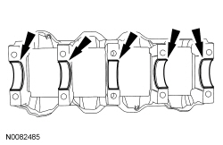
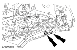
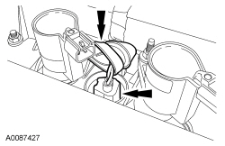
- Lubricate the 10 main bearing beam side fit surfaces (front 2 shown) with clean engine oil.
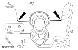
- Lubricate the crankshaft bearing journals on the main bearing beam with clean engine oil. Then position the main bearing beam in the engine block with the main bearing beam mounted flush with the rear face of the engine block.
- NOTE:
Lubricate the main bearing beam bolts threads and under the bolt heads with clean engine oil.
NOTE:
Position the crankshaft to the rear of the cylinder block, then position the crankshaft to the front of the cylinder block before tightening the main bearing beam bolts.
Install and tighten the 10 main bearing beam bolts.- Tighten the bolts in the sequence shown in 3 stages.
- Stage 1: Tighten to 5 Nm (44 lb-in).
- Stage 2: Tighten to 25 Nm (18 lb-ft).
- Stage 3: Tighten an additional 90 degrees.
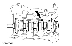
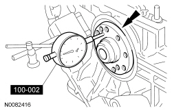
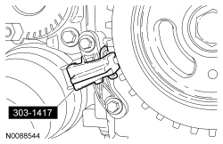
- Using the Dial Indicator Gauge with Holding Fixture, measure crankshaft
end play.
- Position the crankshaft to the rear of the cylinder block.
- Zero the Dial Indicator Gauge with Holding Fixture.
- Move the crankshaft to the front of the cylinder block. Note and record the crankshaft end play.
- Acceptable crankshaft end play is 0.22-0.43 mm (0.008-0.016 in). If the crankshaft end play exceeds the specified range, install new parts as necessary.
- NOTICE: Be sure not to scratch the cylinder wall or crankshaft journal
with the connecting rod. Push the piston down until the connecting rod bearing
seats on the crankshaft journal.
NOTE:
Lubricate the pistons, piston rings, connecting rod bearings and the entire cylinder bores with clean engine oil.
NOTE:
Make sure the piston arrow on top is facing toward the front of the engine.
Using the Piston Ring Compressor and the Connecting Rod Installer, install the piston and connecting rod assemblies.- When installing the pistons and connecting rod assemblies, the oil ring gaps must be positioned 60 degrees apart from each other and a minimum of 90 degrees from the expander gap.
- The position of the upper and lower compression ring gaps are not controlled for installation.
- NOTICE: The rod cap installation must keep the same orientation as marked
during disassembly or engine damage may occur.
NOTE:
Install connecting rod caps and bolts on the connecting rods for cylinders 1 and 4 first and tighten. Then rotate crankshaft 180 degrees and install connecting rod caps and bolts on connecting rods for cylinders 2 and 3 and tighten.
NOTE:
After installation of each connecting rod cap, rotate the crankshaft to verify smooth operation.
Install the connecting rod caps and bolts.- Tighten the bolts in 2 stages.
- Stage 1: Tighten to 29 Nm (21 lb-ft).
- Stage 2: Tighten an additional 90 degrees.
- NOTICE: Failure to position the No. 1 piston at Top Dead Center (TDC)
can result in damage to the engine. Turn the engine in the normal direction
of rotation only.
Turn the crankshaft clockwise to position the No. 1 piston at Top Dead Center (TDC) .
- NOTE:
The Crankshaft TDC Timing Peg will contact the crankshaft and prevent it from turning past TDC . However, the crankshaft can still be rotated in the counterclockwise direction. The crankshaft must remain at the TDC position until the timing drive components and crankshaft pulley are installed.
Install the Crankshaft TDC Timing Peg.
- NOTE:
Clean the oil pump and cylinder block mating surfaces with metal surface prep.
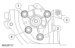
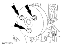
Install the oil pump assembly. Tighten the 4 bolts in the sequence shown in 2 stages.
- Stage 1: Tighten to 10 Nm (89 lb-in).
- Stage 2: Tighten to 20 Nm (177 lb-in).
- Using a new oil pump pickup tube gasket, install the pickup tube and bolts.
- Tighten to 10 Nm (89 lb-in).
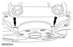
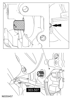
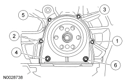
- Using the Crankshaft Rear Main Oil Seal Installer, install the crankshaft rear seal.
- Tighten the 6 crankshaft rear seal with retainer plate bolts in the sequence
shown.
- Tighten to 10 Nm (89 lb-in).
- NOTICE: Do not use metal scrapers, wire brushes, power abrasive discs
or other abrasive means to clean the sealing surfaces. These tools cause scratches
and gouges, which make leak paths. Use a plastic scraping tool to remove traces
of sealant.
Clean and inspect all mating surfaces.
- NOTE:
If the oil pan is not secured within 4 minutes of sealant application, the sealant must be removed and the sealing area cleaned with metal surface prep. Allow to dry until there is no sign of wetness, or 4 minutes, whichever is longer. Failure to follow this procedure can cause future oil leakage.
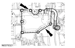
Apply a 2.5 mm (0.09 in) bead of silicone gasket and sealant to the oil pan-to-engine block and to the oil pan-to-engine front cover mating surface.
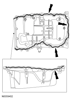
- Install the oil pan. Install the 2 oil pan bolts finger-tight.
- Using a suitable straight edge, align the front surface of the oil pan flush with the front surface of the engine block.
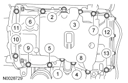
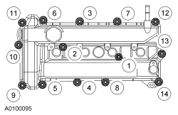
- Install the remaining 13 oil pan bolts and tighten the oil pan bolts in the sequence shown to 25 Nm (18 lb-ft).
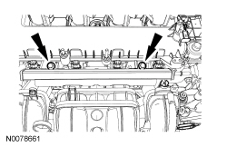
- Install the cylinder head alignment dowels. Dowels must be fully seated in the cylinder block.
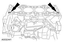
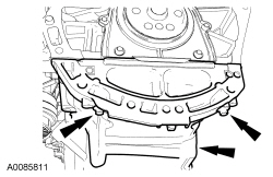
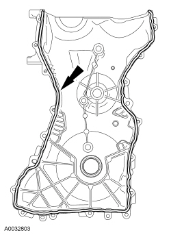
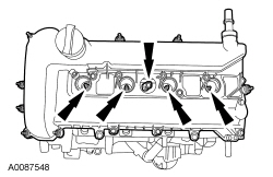
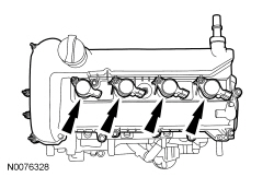
- Apply silicone gasket and sealant to the locations shown.
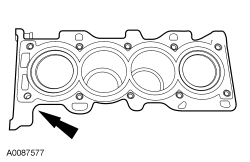
- Install a new cylinder head gasket.
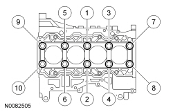
- NOTE:
The cylinder head bolts are torque-to-yield and must not be reused. New cylinder head bolts must be installed.
Install the cylinder head and 10 new bolts. Tighten the bolts in the sequence shown in 5 stages.
- Stage 1: Tighten to 5 Nm (44 lb-in).
- Stage 2: Tighten to 15 Nm (133 lb-in).
- Stage 3: Tighten to 45 Nm (33 lb-ft).
- Stage 4: Turn 90 degrees.
- Stage 5: Turn an additional 90 degrees.
- NOTE:
If the camshafts and valve tappets are to be reused, make sure they are assembled in their original positions.
NOTE:
Coat the valve tappets with clean engine oil.
Install the valve tappets.
- NOTICE: Install the camshafts with the alignment slots in the camshafts
lined up so the Camshaft Alignment Plate can be installed without rotating the
camshafts. Make sure the lobes on the No. 1 cylinder are in the same position
as noted in the disassembly procedure. Rotating the camshafts when the timing
chain is removed, or installing the camshafts 180 degrees out of position, can
cause severe damage to the valves and pistons.
NOTE:
Lubricate the camshaft journals and bearing caps with clean engine oil.
Install the camshafts and bearing caps in their original location and orientation. Tighten the bearing caps in the sequence shown in 3 stages:- Stage 1: Tighten one turn at a time until tight.
- Stage 2: Tighten to 7 Nm (62 lb-in).
- Stage 3: Tighten to 16 Nm (142 lb-in).

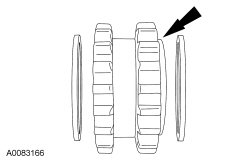
- NOTE:
Install a new crankshaft sprocket diamond washer on both sides of the crankshaft sprocket.
Install the crankshaft sprocket, new crankshaft sprocket diamond washers, oil pump chain and oil pump sprocket.
- The crankshaft sprocket flange must be facing away from the engine block.
- Install the oil pump chain, sprocket and bolt.
- Tighten to 25 Nm (18 lb-ft).
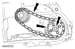
- Install the oil pump chain tensioner shoulder bolt.
- Tighten to 10 Nm (89 lb-in).
- Install the oil pump chain tensioner. Hook the tensioner spring around the
shoulder bolt.
- Tighten to 10 Nm (89 lb-in).
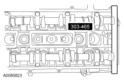
- NOTICE: The Camshaft Alignment Plate is for camshaft alignment only.
Using this tool to prevent engine rotation can result in engine damage.
Install the Camshaft Alignment Plate in the slots on the rear of both camshafts.
- Install the camshaft sprockets and the bolts. Do not tighten the bolts at this time.
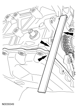
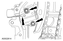
- Install the LH timing chain guide and the 2 bolts.
- Tighten to 10 Nm (89 lb-in).
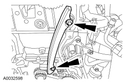
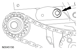
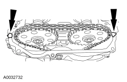
- Install the timing chain.
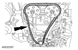
- Install the RH timing chain guide.
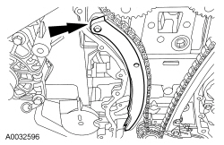
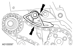
NOTE:
If the timing chain plunger and ratchet assembly are not pinned in the compressed position, follow the next 4 steps.
- NOTICE: Do not compress the ratchet assembly. This will damage the ratchet
assembly.
Using the edge of a vise, compress the timing chain tensioner plunger.
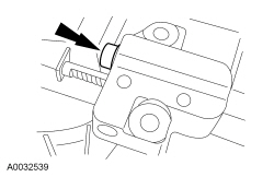
- Using a small pick, push back and hold the ratchet mechanism.
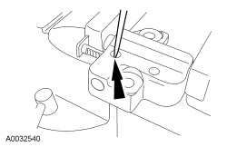
- While holding the ratchet mechanism, push the ratchet arm back into the tensioner housing.
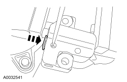
- Install a paper clip into the hole in the tensioner housing to hold the ratchet assembly and the plunger in during installation.
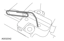
- Install the timing chain tensioner and the 2 bolts. Remove the paper clip
to release the piston.
- Tighten to 10 Nm (89 lb-in).
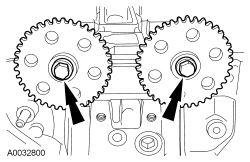
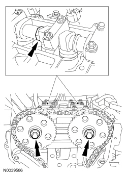
- NOTICE: The Camshaft Alignment Plate is for camshaft alignment only.
Using this tool to prevent engine rotation can result in engine damage.
Using the flats on the camshafts to prevent camshaft rotation, tighten the camshaft drive gear bolts to 72 Nm (53 lb-ft).
- NOTICE: Do not use metal scrapers, wire brushes, power abrasive disks
or other abrasive means to clean sealing surfaces. These tools cause scratches
and gouges which make leak paths.
Clean and inspect the mounting surfaces of the engine and the front cover.
- NOTE:
The engine front cover must be installed and the bolts tightened within 4 minutes of applying the silicone gasket and sealant.
Apply a 2.5 mm (0.10 in) bead of silicone gasket and sealant to the cylinder head and oil pan joint areas. Apply a 2.5 mm (0.10 in) bead of silicone gasket and sealant to the front cover.
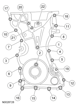
- Install the engine front cover. Tighten the 22 bolts in the sequence shown
to the following specifications:
- Tighten the 8-mm bolts to 10 Nm (89 lb-in).
- Tighten the 13-mm bolts to 48 Nm (35 lb-ft).
- NOTE:
Remove the through-bolt from the Camshaft Front Oil Seal Installer.
NOTE:
Lubricate the oil seal with clean engine oil.
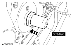
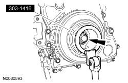
Using the Camshaft Front Oil Seal Installer, install a new crankshaft front seal.
- NOTE:
Do not install the crankshaft pulley bolt at this time.
NOTE:
Apply clean engine oil on the seal area before installing.
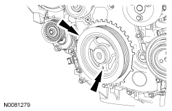
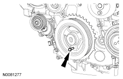
Position the crankshaft pulley onto the crankshaft with the hole in the pulley at the 6 o'clock position.
- NOTICE: Only hand-tighten the 6 mm bolt or damage to the front cover
can occur.
NOTE:
This step will correctly align the crankshaft pulley to the crankshaft.
Install a standard 6 mm x 18 mm bolt through the crankshaft pulley and thread it into the front cover.
- NOTICE: The crankshaft must remain in the Top Dead Center (TDC) position
during installation of the pulley bolt or damage to the engine can occur. Therefore,
the crankshaft pulley must be held in place with the Crankshaft Damper Holding
Tool and the bolt should be installed using hand tools only.
NOTE:
Do not reuse the crankshaft pulley bolt.
Install a new crankshaft pulley bolt. Using the Crankshaft Damper Holding Tool to hold the crankshaft pulley in place, tighten the crankshaft pulley bolt in 2 stages:- Stage 1: Tighten to 100 Nm (74 lb-ft).
- Stage 2: Tighten an additional 90 degrees (one-fourth turn).
- Remove the 6 mm x 18 mm bolt.
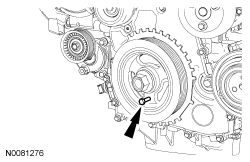
- Remove the Crankshaft TDC Timing Peg.
- Remove the Camshaft Alignment Plate.
- NOTE:
Only turn the engine in the normal direction of rotation.
Turn the crankshaft clockwise one and three-fourths turn.
- Install the Crankshaft TDC Timing Peg.
- NOTE:
Only turn the engine in the normal direction of rotation.
Turn the crankshaft clockwise until the crankshaft contacts the Crankshaft TDC Timing Peg.
- NOTICE: Only hand-tighten the bolt or damage to the front cover can occur.
Using the 6 mm x 18 mm bolt, check the position of the crankshaft pulley.
- If it is not possible to install the bolt, the engine valve timing must be corrected.
- Install the Camshaft Alignment Plate to check the position of the camshafts.
- If it is not possible to install the Camshaft Alignment Plate, the engine valve timing must be corrected.
- Remove the Camshaft Alignment Plate.
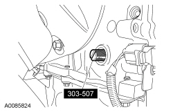
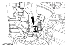
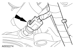
- Install the Crankshaft Position (CKP) sensor and the 2 bolts.
- Do not tighten the bolts at this time.
- Using the Crankshaft Sensor Aligner, adjust the CKP sensor.
- Tighten the 2 CKP bolts to 7 Nm (62 lb-in).
- Remove the 6 mm x 18 mm bolt.
- Remove the Crankshaft TDC Timing Peg.
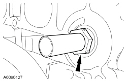
- Install the engine plug bolt.
- Tighten to 20 Nm (177 lb-in).
- NOTICE: Do not use metal scrapers, wire brushes, power abrasive discs
or other abrasive means to clean the sealing surfaces. These tools cause scratches
and gouges which make leak paths.
Clean the valve cover gasket surface with metal surface prep.
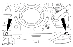
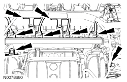
- Apply silicone gasket and sealant to the locations shown.
- NOTE:
The valve cover must be secured within 4 minutes of silicone gasket application. If the valve cover is not secured within 4 minutes, the sealant must be removed and the sealing area cleaned with metal surface prep.
Install the valve cover.
- Tighten the 14 bolts in the sequence shown to 10 Nm (89 lb-in).
- NOTICE: Only use hand tools when removing or installing the spark plugs,
damage can occur to the cylinder head or spark plug.
Install the Cylinder Head Temperature (CHT) sensor and the spark plugs.
- Tighten the CHT sensor to 12 Nm (106 lb-in).
- Tighten the spark plugs to 12 Nm (106 lb-in).
- NOTE:
Apply dielectric compound to the inside of the coil-on-plug boots.
Install the 4 ignition coil-on-plugs and the 4 bolts.
- Tighten to 10 Nm (89 lb-in).
- If equipped, install the engine block heater.
- Tighten to 40 Nm (30 lb-ft).
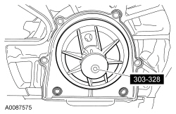
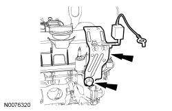
- Install the crankcase vent oil separator and the 8 bolts.
- Tighten to 10 Nm (89 lb-in).
- NOTE:
The Knock Sensor (KS) must not touch the crankcase vent oil separator.
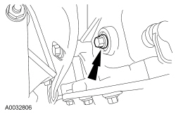
Install the KS and the bolt.
- Tighten to 20 Nm (177 lb-in).
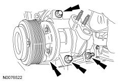
- Install the A/C compressor, 2 bolts and the stud bolt.
- Tighten to 25 Nm (18 lb-ft).
- NOTE:
Clean and inspect the thermostat housing gasket. Install a new gasket if necessary.
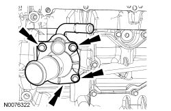
Install the thermostat housing and 3 bolts.
- Tighten to 10 Nm (89 lb-in).
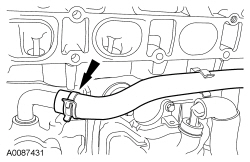
- Connect the coolant bypass hose.
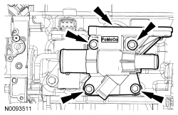
- Using a new gasket, install the coolant outlet and the 4 bolts.
- Tighten to 10 Nm (89 lb-in).
- Connect the coolant bypass hose.
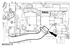
- Connect the EGR valve coolant hose.
- Install the radio interference capacitor bracket and bolt.
- Tighten to 10 Nm (89 lb-in).
- Install the EGR tube.
- Tighten to 55 Nm (41 lb-ft).
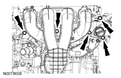
- Inspect and install new intake manifold gaskets if necessary.
- NOTICE: If the engine is repaired or replaced because of upper engine
failure, typically including valve or piston damage, check the intake manifold
for metal debris. If metal debris is found, install a new intake manifold. Failure
to follow these instructions can result in engine damage.
Position the intake manifold and connect the PCV hose.
- NOTE:
The 2 intake manifold bolts differ in length from rest of the bolts and also retain a crash bracket to the intake manifold. The 2 bolts are equipped with an attachment feature that allows them to be loosened but remain attached to the intake manifold. Do not attempt to remove the 2 bolts or the crash bracket from the intake manifold.
Install the intake manifold and hand-tighten the 2 intake manifold bolts.
- Install the 5 intake manifold mounting bolts.
- Tighten all 7 bolts to 18 Nm (159 lb-in).
- Install the lower intake manifold bolt.
- Tighten to 18 Nm (159 lb-in).
- NOTE:
Lubricate the new O-ring with clean engine oil.
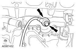
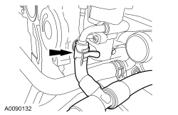
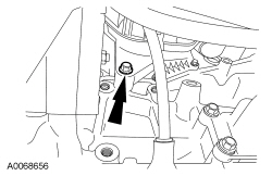
Using a new O-ring seal, install the oil level indicator tube assembly and the bolt.
- Tighten to 10 Nm (89 lb-in).
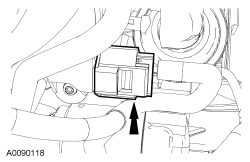
- Connect the EGR valve electrical connector and if equipped, connect the swirl control valve sensor electrical connector.
- If equipped, connect the swirl control valve solenoid electrical connector.
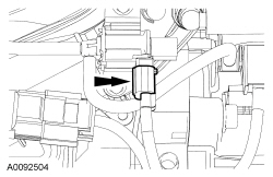
- Connect the Manifold Absolute Pressure (MAP) electrical connector.
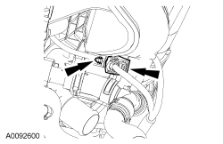
- Connect the KS electrical connector and pin-type retainer.
- NOTICE: Use O-ring seals that are made of special fuel-resistant material.
Use of ordinary O-rings can cause the fuel system to leak. Do not reuse the
O-ring seals.
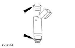
Install new fuel injector O-rings.
- Separate the fuel injectors from the fuel rail.
- Remove and discard the fuel injector O-rings.
- Install new O-rings and lubricate with clean engine oil.
- Install the fuel injectors onto the fuel rail.
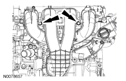
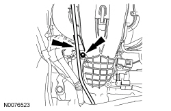
- Install the fuel rail with the fuel injectors and the 2 bolts.
- Tighten to 25 Nm (18 lb-ft).
- Connect the 4 fuel injector electrical connectors and attach the wiring harness retainers to valve cover stud bolts and intake manifold.
- Position the engine control wiring harness on the engine and connect the CHT sensor and install the rubber boot.
- Connect the 4 coil-on-plug and Camshaft Position (CMP) sensor electrical connectors.
- NOTE:
Clean the gasket mating surfaces with metal surface prep.
Using a new gasket, install the oil filter adapter and the 4 bolts.
- Tighten to 25 Nm (18 lb-ft).
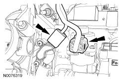
- Connect the Engine Oil Pressure (EOP) switch electrical connector.
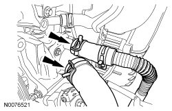
- Connect the heater hose and lower radiator hose to the thermostat housing.
- NOTE:
Clean the coolant pump mating surface with metal surface prep.
NOTE:
Lubricate the coolant pump O-ring with clean engine coolant.
Position the coolant pump and install the 3 bolts.- Tighten to 10 Nm (89 lb-in).
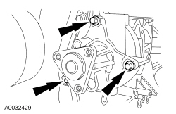
- Install the coolant pump pulley and 3 bolts.
- Tighten to 20 Nm (177 lb-in).
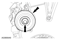
- Install the accessory drive belt idler pulley.
- Tighten to 25 Nm (18 lb-ft).
- Using the Floor Crane and Spreader Bar, remove the engine from the engine stand.
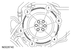
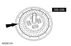
- Install the flexplate or flywheel and the 6 bolts. Tighten the bolts in
the sequence shown in 3 stages:
- Stage 1: Tighten to 50 Nm (37 lb-ft).
- Stage 2: Tighten to 80 Nm (50 lb-ft).
- Stage 3: Tighten to 112 Nm (83 lb-ft).
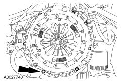
Engines equipped with a manual transaxle
- Lubricate the transaxle input shaft pilot bearing with front axle grease.
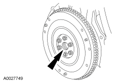
- Using the Clutch Disc Aligner, position the clutch disc on the flywheel.
- NOTE:
If reusing the clutch pressure plate and flywheel, align the marks made during removal.
Position the clutch pressure plate and install the 7 bolts. Tighten the bolts in a star pattern sequence to 27 Nm (20 lb-ft).
 Intake Manifold
Item
Part Number
Description
1
9288
Fuel supply tube
2
8K556
Coolant outlet
3
9D475
EGR valve
4
9E926
Thrott ...
 Engine - 2.0L - Description and Operation
The 2.0L 4-cylinder engine has the following features:
Dual overhead camshaft
Four valves per cylinder
Sequential Multi-Port Fuel Injection (SFI)
Aluminum cylinder head
Aluminum cylin ...
More about Ford Focus:
Ford Focus Evaporative Emissions
NOTE: The vehicle emission vacuum routing diagrams are contained in
the Description and Operation subsection of the Engine Emissions Control section.
Refer to Section 303-08.
The Evaporative Emission (EVAP) system consists of the:
EVAP canister purge valve.
EVAP canister.
EVAP ...
Nissan Frontier - Instrument Panel - Keys - Brake system
