Ford Focus Service Manual: Clutch Master Cylinder
| Item | Specification |
|---|---|
| High Performance DOT 3 Motor Vehicle Brake Fluid PM-1-C (US); CPM-1-C (Canada) | WSS-M6C62-A or WSS-M6C65-A1 |
| Item | Part Number | Description |
|---|---|---|
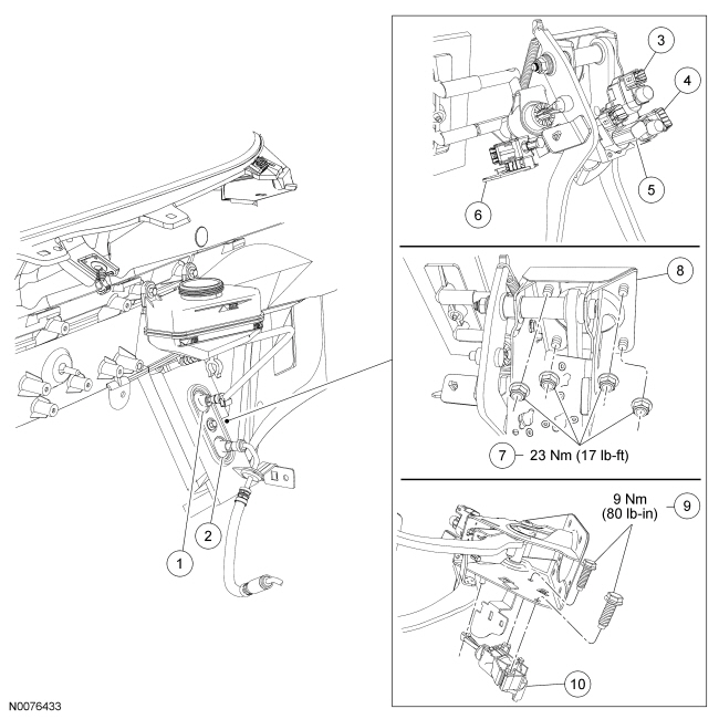
| 1 | — | Upper hydraulic tube |
| 2 | — | Lower hydraulic tube |
| 3 | — | Speed control deactivation switch |
| 4 | — | Stoplamp switch |
| 5 | — | Starter safety switch |
| 6 | 11A152 | Clutch Pedal Position (CPP) switch |
| 7 | — | Clutch pedal assembly nuts (4 required) |
| 8 | 7A564 | Clutch pedal assembly |
| 9 | — | Clutch master cylinder bolts (2 required) |
| 10 | 7A543 | Clutch master cylinder |
Removal
 WARNING: Carefully
read cautionary information on product label. For EMERGENCY MEDICAL INFORMATION
seek medical advice. In the USA or Canada on Ford/Motorcraft products call: 1-800-959-3673.
For additional information, consult the product Material Safety Data Sheet (MSDS)
if available. Failure to follow these instructions may result in serious personal
injury.
NOTICE: Do not spill brake fluid on painted or plastic surfaces or damage to the surface may occur. If brake fluid is spilled onto a painted or plastic surface, immediately wash the surface with water.
- Disconnect the battery ground cable. For additional information, refer to Section 414-01.
- Using a suitable tool, remove brake fluid from the brake fluid reservoir until the brake fluid level is at the MIN mark. Reinstall the brake fluid reservoir cap.
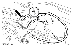
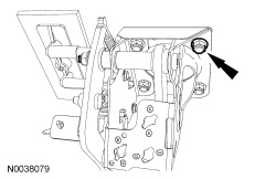
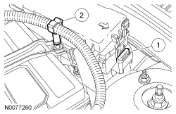
- Remove the Battery Junction Box (BJB) bolt.
- Remove the BJB from the mounting bracket.
- Detach the wiring harness retainer.
- Release the BJB retainer clip and position the BJB aside.

- NOTE:
Cap the upper hydraulic and lower hydraulic supply tubes to prevent fluid loss.
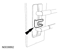
Remove the clips, then disconnect the clutch hydraulic tubes.
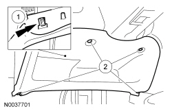
- Remove the instrument panel lower panel from the instrument panel.
- Remove the screws.
- Release the fastener.
- Remove the instrument panel lower panel.
- Detach the Data Link Connector (DLC) .
- Disconnect the hood release cable.
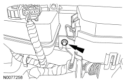
- Remove the clip, then disconnect the upper hydraulic tube from the front bulkhead.
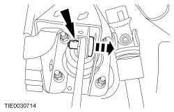
- Depress the locking tang and remove the brake pedal actuating rod retaining pin.
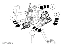
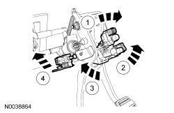
- Disconnect the starter safety switch, clutch position switch, speed control deactivation switch and brake lamp switch electrical connectors from the pedal assembly.
- Remove the switches from the pedal assembly.
- Speed control deactivation switch (green).
- Stoplamp switch (grey).
- Clutch position switch (red).
- Starter safety switch (black).
- NOTE:
The complete clutch pedal assembly and the clutch master cylinder must be removed to gain access to the clutch master cylinder bolts.
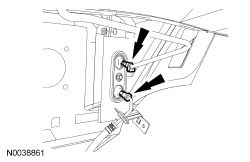
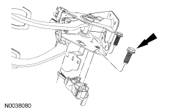
Remove the 4 clutch pedal assembly nuts and the clutch pedal assembly.
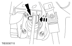
- Mount the pedal assembly in a suitable vise. Remove the 2 clutch master cylinder bolts. Detach the clutch master cylinder from the pedal assembly and slide the actuating rod from the pedal arm.
Installation
- Attach the clutch master cylinder to the clutch pedal assembly. Attach the
actuating rod to the pedal arm. Install the 2 clutch master cylinder bolts.
- Tighten to 9 Nm (80 lb-in).
- Position the clutch pedal assembly in the vehicle.
- NOTE:
Make sure the brake pedal actuating rod retaining pin is locked in position. When correctly installed, the locking tab on the side of the retaining pin will be visible as it extends through the actuating rod and the brake pedal. Push and pull the retaining pin to make sure it is correctly installed.
Install the brake pedal actuating rod retaining pin.
- Install the 4 clutch pedal assembly nuts.
- Tighten to 23 Nm (17 lb-ft).
- Attach the lower hydraulic tube to the front bulkhead and install the clip.
- NOTE:
The clutch position switch (red) is not adjustable.
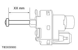
Pull out the starter safety switch, speed control deactivation switch and brake lamp switch plungers until they are fully extended.
- Measure the plunger length.
- Speed control deactivation switch (green) XX mm = 24 mm (0.94 in).
- Brake lamp switch (grey) XX mm = 21 mm (0.82 in).
- Starter safety switch (black) XX mm = 26 mm (1.02 in).
- Measure the plunger length.
- NOTICE: When installing the switches, the brake lamp switch is rotated
counterclockwise and the remaining switches are rotated clockwise. Failure to
follow this instruction will result in the switch plungers binding inside the
switch.
NOTE:
The speed control deactivation switch and the stoplamp switch are automatically adjusted during installation.
NOTE:
A slight ratcheting noise and feel during installation of the speed control deactivation switch and the brake lamp switch is normal.
Install the switches to the pedal assembly.- Speed control deactivation switch (green).
- Brake lamp switch (grey).
- Clutch position switch (red).
- Starter safety switch (black).
- NOTE:
The colors of the electrical connectors and the switches are identical.
Connect the electrical connectors to the pedal assembly switches.
- NOTE:
A slight ratcheting noise and feel during switch adjustment is normal.
Adjust the starter safety switch (black) by pressing and then releasing the clutch pedal.
- NOTE:
Install new O-ring seals.
Connect the clutch master cylinder and slave cylinder fluid supply tubes to the clutch master cylinder, then insert the clips.
- Connect the hood release cable and the DLC to the instrument panel lower panel.
- Install the instrument panel lower panel trim to the instrument panel.
- Secure the fastener.
- Install the screws.
- Install the BJB to the mounting bracket.
- Position the BJB and attach to the retainer clip.
- Attach the wiring harness retainer.
- Install the BJB bolt.
- Fill the brake fluid reservoir to the MAX mark with the specified fluid.
- Bleed the hydraulic clutch system. For additional information, refer to Section 308-00.
- Connect the battery ground cable. For additional information, refer to Section 414-01.
 Clutch Disc and Pressure Plate
Clutch Components
Item
Part Number
Description
1
—
Clutch pressure plate-to-flywheel bolt (6 required)
2
7563
Clutch pressure plate
...
 Clutch Slave Cylinder
Item
Part Number
Description
1
—
Clutch slave cylinder bolt (3 required)
2
7A508
Clutch slave cylinder
Removal
WARNING: Carefully ...
More about Ford Focus:
Ford Focus Fuel System Pressure Release
WARNING: Do not
smoke, carry lighted tobacco or have an open flame of any type when working on or
near any fuel-related component. Highly flammable mixtures are always present and
may be ignited. Failure to follow these instructions may result in serious personal
injury.
WARNING: Do not
...
Nissan Frontier - Instrument Panel - Keys - Brake system
