Ford Focus Service Manual: Pyrotechnic Device Disposal
Disposal of Deployable Devices and Pyrotechnic Devices That are Undeployed/Inoperative
NOTE:
All inoperative air bag modules and safety belt pretensioners have been placed on the Mandatory Return List. All discolored or damaged air bag modules must be treated the same as any inoperative live air bag being returned.
- Depower the SRS . Refer to Supplemental Restraint System (SRS) Depowering and Repowering in the General Procedures portion of this section.
- Remove the undeployed/inoperative device. Refer to the appropriate procedure in this section or Section 501-20A.
- NOTE:
When installing a new air bag module or inflatable safety belt inflator, a prepaid return postcard is provided with the replacement air bag module. The serial number for the new part and the VIN must be recorded and sent to Ford Motor Company.
If installing a new air bag module or inflatable safety belt inflator, record the necessary information and return the inoperative air bag module to Ford Motor Company.
Disposal of Deployable Devices and Pyrotechnic Devices That Are Deployed
- Depower the SRS . Refer to Supplemental Restraint System (SRS) Depowering and Repowering in the General Procedures portion of this section.
- Remove the deployed device. Refer to the appropriate procedure in this section or Section 501-20A.
- NOTE:
If a dual stage driver or passenger air bag module has deployed due to a crash event, the air bag module requires manual deployment to make sure both stages and the active canister vent have deployed before scrapping the vehicle or disposing of the air bag module. To determine if a vehicle is equipped with dual stage driver or passenger air bag modules, refer to the Description and Operation portion of this section.
Dispose of the deployed device in the same manner as any other part to be scrapped.
Disposal of Deployable Devices and Pyrotechnic Devices That Require Manual Deployment
- Safety and environmental concerns require consideration and treatment of
restraints system deployable and pyrotechnic devices when disposing of vehicles,
deployable devices or pyrotechnic devices. Deploying deployable and pyrotechnic
devices before scrapping a vehicle or the device eliminates the potential for
hazardous exposures or reactions during processing. If special handling procedures
are followed, deployable and pyrotechnic devices can be deployed safely and
recycled with the vehicle, shipped separately to a recycling facility or disposed
of safely.
NOTE:
To determine the deployable devices a vehicle is equipped with, refer to the Description and Operation portion of this section.
A vehicle equipped with any of the following deployable devices requires manual deployment of the devices before scrapping the vehicle or component. Refer to the appropriate portion of this procedure.- Driver air bag module
- Inflatable safety belt inflators
- Knee air bag module
- Passenger air bag module
- Seat side air bag modules
- Safety Canopy® modules
- Side air curtain modules
- NOTE:
To determine the pyrotechnic devices a vehicle is equipped with, refer to the Description and Operation portion of this section.
A vehicle equipped with any of the following pyrotechnic devices requires manual deployment of the devices before scrapping the vehicle or component. Refer to the appropriate portion of this procedure.
- Safety belt buckle pretensioners
- Safety belt retractor pretensioners
- Safety belt anchor pretensioners
- Adaptive load-limiting retractors
- Deployable steering column
- NOTE:
To determine if a vehicle is equipped with dual stage driver or passenger air bag modules, refer to the Description and Operation portion of this section.
If a dual stage driver or passenger air bag module has deployed due to a crash event, the air bag module requires manual deployment to make sure both stages and the active canister vent have deployed before scrapping the vehicle or disposing of the air bag module. Refer to Driver Air Bag Module, Passenger Air Bag Module, Knee Air Bag Module and Seat Side Air Bag Module` — Remote Deployment in this procedure.
Driver Air Bag Module, Passenger Air Bag Module, Knee Air Bag Module and Seat Side Air Bag Module — Remote Deployment
 WARNING: Never
probe the electrical connectors on airbag, Safety Canopy or side air curtain assemblies.
Failure to follow this instruction may result in the accidental deployment of these
assemblies, which increases the risk of serious personal injury or death.
WARNING: Always
carry a live airbag with the deployment door, trim cover or tear seam pointed away
from the body. Do not place a live airbag down with the deployment door, trim cover
or tear seam facing down. Failure to follow these instructions may result in serious
personal injury in the event of an accidental deployment.
WARNING: Always
carry a live Safety Canopy or side air curtain assembly with the tear seam pointed
away from your body. Failure to follow this instruction may result in serious personal
injury or death in the event of an accidental deployment.
WARNING: Deploy
all supplemental restraint system (SRS) devices (airbags, pretensioners, load limiters,
etc.) outdoors with all personnel at least 9 meters (30 feet) away to make sure
of personal safety. Due to the loud report which occurs when an SRS device is deployed,
hearing protection is required. Failure to follow these instructions may result
in serious personal injury.
NOTE:
For air bag modules with multiple loops, deploy all of the loops on the air bag module.
NOTE:
Some driver and passenger front air bags have 2 deployment stages and an active canister vent. After a collision it is possible that Stage 1 has deployed and Stage 2 and the active canister vent have not.
If a front air bag module has deployed, it is mandatorythat the front air bag module be remotely deployed using the appropriate air bag disposal procedure.
NOTE:
A typical air bag disposal is shown that is similar for all vehicles.
All driver, passenger, knee and seat side air bag modules
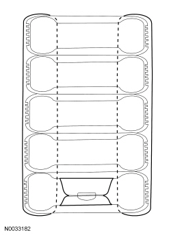
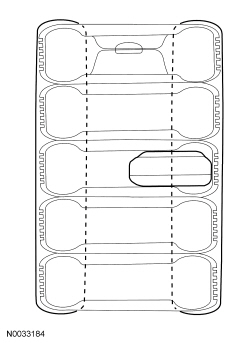
- Make a container to house the air bag module for deployment.
- NOTE:
The tires must be of sufficient size to accommodate the air bag module.
Obtain a tire and wheel assembly and an additional 4 tires (without wheels) of the same size.
- With the tire and wheel assembly on the bottom, stack the tires.
- Securely tie all of the tires together.
- NOTE:
- Depower the SRS . Refer to Supplemental Restraint System (SRS) Depowering and Repowering in the General Procedures portion of this section.
- Remove the air bag module. Refer to the appropriate procedure in this section.
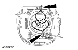
- NOTE:
If the air bag module does not have a hard-wired pigtail, cut the wires and connector(s) from the vehicle wire harness and reconnect to the air bag module.
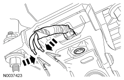
Cut each of the air bag module wires near the electrical connector that connects to the vehicle wire harness.
- Remove any sheathing (if present) and strip the insulation from the ends of the cut wires.
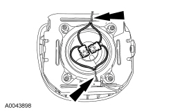
- NOTE:
Typical driver air bag module with 2 loops shown, other air bag modules with multiple loops or multiple features (canister vent, active tether) similar.
For air bag modules with multiple loops, twist together a wire from each loop then repeat for the remaining wires from each loop.
- Make a jumper harness to deploy the air bag module.
- Obtain 2 wires (20 gauge minimum) at least 9.14 m (30 ft) long and strip both ends of each wire.
- At one end of the jumper harness, connect the wires together.
- Using the end of the jumper harness where the wires are not connected together, attach each wire of the jumper harness to each wire of the air bag module or to the twisted-together wires if multiple loops. Use tape or other insulating material to make sure that the leads do not make contact with each other.
Driver air bag modules
- NOTE:
Make sure the air bag connections are maintained.
For driver air bag modules, with the stack of tires upright and the wheel on the bottom, carefully place the driver air bag module, with the trim cover facing up, on the wheel.
Passenger, knee and seat side air bag modules
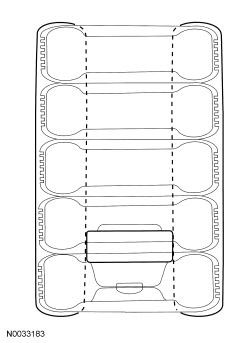
- NOTE:
Make sure the air bag connections are maintained.
Tip the stack of tires on its side and place the air bag module inside the center tire, making sure that there are 2 tires beneath the tire containing the air bag module and 2 tires (including the tire and wheel assembly) above the tire containing the air bag module.
- Place the tire stack upright, with the wheel on top.
All driver, passenger, knee and seat side air bag modules
- Remain at least 9.14 m (30 ft) away from the air bag module.
- From the end of the jumper harness that is not connected to the air bag module, disconnect the 2 wires of the jumper harness from each other.
- Deploy the air bag module by touching the ends of the 2 wires of the jumper harness to the terminals of a 12-volt battery.
- To allow for cooling, wait at least 10 minutes before approaching the deployed air bag module.
- Dispose of the deployed air bag module in the same manner as any other part to be scrapped.
Safety Belt Anchor Pretensioners, Safety Belt Buckle Pretensioners, Safety Belt Retractor Pretensioners, Adaptive Load Limiting Safety Belt Retractors and Safety Belt Inflators — Remote Deployment
WARNING: Never
disassemble or tamper with seat belt deployable components, including pretensioners,
load limiters and inflators. Never back probe deployable device electrical connectors.
Tampering or back probing may cause an accidental deployment and result in personal
injury or death.
WARNING: Deploy
all supplemental restraint system (SRS) devices (airbags, pretensioners, load limiters,
etc.) outdoors with all personnel at least 9 meters (30 feet) away to make sure
of personal safety. Due to the loud report which occurs when an SRS device is deployed,
hearing protection is required. Failure to follow these instructions may result
in serious personal injury.
NOTE:
A typical safety belt buckle, retractor and inflator disposal is shown that is similar for all vehicles.
- Make a container to house the safety belt buckle or retractor for deployment.
- NOTE:
The tires must be of sufficient size to accommodate the safety belt buckle, retractor or inflator.
Obtain a tire and wheel assembly and 4 additional tires (without wheels) of the same size.
- With the tire and wheel assembly on the bottom, stack the tires.
- Securely tie all of the tires together.
- NOTE:
- Depower the SRS . Refer to Supplemental Restraint System (SRS) Depowering and Repowering in the General Procedures portion of this section.
- Remove the safety belt buckle, retractor or inflator. Refer to the appropriate
procedure in Section 501-20A.
- When deploying a safety belt buckle pretensioner, install a nut and bolt of sufficient length and of the same diameter as was used to retain it to the seat.
- NOTE:
If the safety belt anchor, buckle, retractor or inflator does not have a hard-wired pigtail, it will be necessary to cut the wires and connector(s) from the vehicle wire harness and reconnect to the safety belt buckle, retractor or inflator.
Cut each of the safety belt anchor, buckle, retractor or inflator wires near the electrical connector that connects to the vehicle wire harness.
- Remove any sheathing (if present) and strip the insulation from the ends of the cut wires.
- Make a jumper harness to deploy the safety belt buckle, retractor or inflator.
- Obtain 2 wires (20 gauge minimum) at least 9.14 m (30 ft) long and strip both ends of each wire.
- At one end of the jumper harness, connect the wires together.
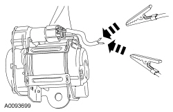
- NOTE:
Typical safety belt retractor pretensioner shown, other safety belt anchor pretensioners, buckle pretensioners, load-limiting retractors and safety belt inflators similar.
Using the end of the jumper harness that the wires are not connected together, attach each wire of the jumper harness to each wire of the safety belt anchor, buckle, retractor or inflator. Use tape or other insulating material to make sure that the leads do not make contact with each other.
- NOTE:
Make sure the safety belt anchor, buckle, retractor or inflator connections are maintained.
Tip the stack of tires on its side and place the safety belt anchor, buckle, retractor or inflator inside the center tire, making sure that there are 2 tires beneath the tire containing the safety belt anchor, buckle, retractor or inflator and 2 tires (including the tire and wheel assembly) above the tire containing the safety belt anchor, buckle, retractor or inflator.
- Place the tire stack upright, with the wheel on top.
- Remain at least 9.14 m (30 ft) away from the safety belt anchor, buckle, retractor or inflator.
- From the end of the jumper harness that is not connected to the safety belt anchor, buckle, retractor or inflator, disconnect the 2 wires of the jumper harness from each other.
- Deploy the safety belt anchor pretensioner, buckle pretensioner, retractor pretensioner or inflator by touching the ends of the 2 wires of the jumper harness to the terminals of a 12-volt battery.
- To allow for cooling, wait at least 10 minutes before approaching the deployed safety belt anchor pretensioner, buckle pretensioner, retractor pretensioner or inflator.
- Dispose of the deployed safety belt anchor, buckle, retractor or inflator in the same manner as any other part to be scrapped.
Safety Belt Anchor Pretensioners, Safety Belt Buckle Pretensioners, Safety Belt Retractor Pretensioners and Load Limiting Safety Belt Retractors — In-Vehicle Deployment
WARNING: Never
disassemble or tamper with seat belt deployable components, including pretensioners,
load limiters and inflators. Never back probe deployable device electrical connectors.
Tampering or back probing may cause an accidental deployment and result in personal
injury or death.
WARNING: Deploy
all supplemental restraint system (SRS) devices (airbags, pretensioners, load limiters,
etc.) outdoors with all personnel at least 9 meters (30 feet) away to make sure
of personal safety. Due to the loud report which occurs when an SRS device is deployed,
hearing protection is required. Failure to follow these instructions may result
in serious personal injury.
NOTE:
A typical safety belt buckle and retractor disposal is shown that is similar for all vehicles.
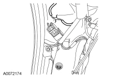
- Depower the SRS . Refer to Supplemental Restraint System (SRS) Depowering and Repowering in the General Procedures portion of this section.
- Access the safety belt anchor, buckle or retractor electrical connectors. For additional information, refer to Section 501-20A.
- Cut each of the safety belt anchor, buckle or retractor wires, leaving at least 101.6 mm (4 in) to work with.
- Remove any sheathing (if present) and strip the insulation from the ends of the cut wires.
- Make a jumper harness to deploy the safety belt anchor, buckle or retractor.
- Obtain 2 wires (20 gauge minimum) at least 9.14 m (30 ft) long and strip both ends of each wire.
- At one end of the jumper harness, connect the wires together.
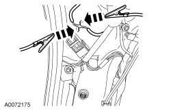
- NOTE:
Typical safety belt retractor pretensioner shown, other safety belt anchor pretensioners, buckle pretensioners and load-limiting retractors are similar.
Using the end of the jumper harness that the wires are not connected together, attach each wire of the jumper harness to each wire of the safety belt anchor, buckle or retractor. Use tape or other insulating material to make sure that the leads do not make contact with each other.
- Remain at least 9.14 m (30 ft) away from the safety belt anchor, buckle or retractor.
- From the end of the jumper harness that is not connected to the safety belt anchor, buckle or retractor, disconnect the 2 wires of the jumper harness from each other.
- Deploy the safety belt anchor pretensioner, buckle pretensioner or retractor pretensioner by touching the ends of the 2 wires of the jumper harness to the terminals of a 12-volt battery.
- To allow for cooling, wait at least 10 minutes before approaching the deployed safety belt anchor pretensioner, buckle pretensioner or retractor pretensioner.
- Dispose of the deployed safety belt anchor, buckle or retractor in the same manner as any other part to be scrapped.
Safety Canopy® Modules and Side Air Curtain Modules — In-Vehicle Deployment
WARNING: Deploy
all supplemental restraint system (SRS) devices (airbags, pretensioners, load limiters,
etc.) outdoors with all personnel at least 9 meters (30 feet) away to make sure
of personal safety. Due to the loud report which occurs when an SRS device is deployed,
hearing protection is required. Failure to follow these instructions may result
in serious personal injury.
NOTE:
The Safety Canopy® module deployment for a scrapped vehicle will occur in its installed position in the vehicle.
NOTE:
A typical Safety Canopy® module disposal is shown that is similar for all vehicles.
- Depower the SRS . Refer to Supplemental Restraint System (SRS) Depowering and Repowering in the General Procedures portion of this section.
- Access the Safety Canopy®/side air curtain module electrical connectors. For additional information, refer to the appropriate procedure in this section.
- Cut each of the Safety Canopy®/side air curtain module wires leaving at least 101.6 mm (4 in) to work with.
- Remove any sheathing (if present) and strip the insulation from the ends of the cut wires.
- NOTE:
Typical Safety Canopy®/side air curtain module with 2 loops shown, other Safety Canopy®/side air curtain modules with 2 loops are similar.
For Safety Canopy®/side air curtain modules with multiple loops, twist together a wire from each loop then repeat for the remaining wires from each loop.
- Make a jumper harness to deploy the Safety Canopy®/side air curtain module.
- Obtain 2 wires (20 gauge minimum) at least 9.14 m (30 ft) long and strip both ends of each wire.
- At one end of the jumper harness, connect the wires together.
- Using the end of the jumper harness where the wires are not connected together, attach each wire of the jumper harness to each wire of the Safety Canopy®/side air curtain module or to the twisted-together wires if multiple loops. Use tape or other insulating material to make sure that the leads do not make contact with each other.
- From the end of the jumper harness that is not connected to the Safety Canopy®/side air curtain module, disconnect the 2 wires of the jumper harness from each other.
- Deploy the Safety Canopy®/side air curtain module by touching the ends of the 2 wires of the jumper harness to the terminals of a 12-volt battery.
- To allow for cooling, wait at least 10 minutes before approaching the deployed Safety Canopy®/side air curtain module.
- Dispose of the deployed Safety Canopy®/side air curtain module in the same manner as any other part to be scrapped.
Deployable Steering Column — In-Vehicle Deployment
WARNING: Deploy
all supplemental restraint system (SRS) devices (airbags, pretensioners, load limiters,
etc.) outdoors with all personnel at least 9 meters (30 feet) away to make sure
of personal safety. Due to the loud report which occurs when an SRS device is deployed,
hearing protection is required. Failure to follow these instructions may result
in serious personal injury.
- Depower the SRS . Refer to Supplemental Restraint System (SRS) Depowering and Repowering in the General Procedures portion of this section.
- NOTE:
It may be necessary to lower or remove the deployable steering column from the instrument panel to access the deployable steering column electrical connector.
Access the deployable steering column electrical connector.
- NOTE:
If the deployable steering column does not have a hard-wired pigtail, it will be necessary to cut the wires and connector(s) from the vehicle wire harness and reconnect to the deployable steering column.
Cut each of the deployable steering column wires, leaving at least 101.6 mm (4 in) to work with.
- Remove any sheathing (if present) and strip the insulation from the ends of the cut wires.
- Make a jumper harness to deploy the deployable steering column.
- Obtain 2 wires (20 gauge minimum) at least 9.14 m (30 ft) long and strip both ends of each wire.
- At one end of the jumper harness, connect the wires together.
- Using the end of the jumper harness where the wires are not connected together, attach each wire of the jumper harness to each wire of the deployable steering column. Use tape or other insulating material to make sure that the leads do not make contact with each other.
- Remain at least 9.14 m (30 ft) away from the deployable steering column.
- From the end of the jumper harness that is not connected to the deployable steering column, disconnect the 2 wires of the jumper harness from each other.
- Deploy the deployable steering column by touching the ends of the 2 wires of the jumper harness to the terminals of a 12-volt battery.
- To allow for cooling, wait at least 10 minutes before approaching the deployed steering column.
- Dispose of the deployed steering column in the same manner as any other part to be scrapped.
 Inspection and Repair After a Supplemental Restraint System (SRS) Deployment
WARNING: Remove
restraint system diagnostic tools from the vehicle prior to road testing. If tools
are not removed, the supplemental restraint system (SRS) device may not deploy in
a crash. Fail ...
 Supplemental Restraint System (SRS) Deactivation and Reactivation
Deactivation
WARNING: Always
carry a live airbag with the deployment door, trim cover or tear seam pointed away
from the body. Do not place a live airbag down with the deployment door, trim cove ...
More about Ford Focus:
Ford Focus Safety Belt Shoulder Height Adjuster
NOTE: LH shown, RH similar.
Item
Part Number
Description
1
602B82
Safety belt shoulder height adjuster
2
—
Safety belt height adjuster bolt (part of 602B82)
Removal and Installation
WARNING: After
any crash, all of the follow ...
Nissan Frontier - Instrument Panel - Keys - Brake system
