Ford Focus Service Manual: Steering Column - Removal and Installation
| Item | Part Number | Description |
|---|---|---|
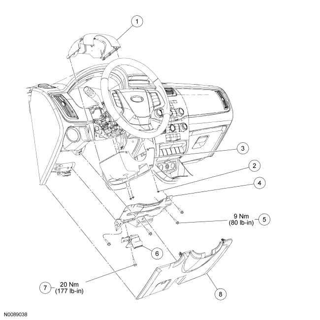
| 1 | 3530 | Upper steering column shroud |
| 2 | W713494 | Lower steering column shroud screw (3 required) |
| 3 | 3530 | Lower steering column shroud |
| 4 | 54017A28 | Steering column opening reinforcement |
| 5 | W701928 | Steering column opening reinforcement bolt (4 required) |
| 6 | 16916 | Hood release handle and cable |
| 7 | W505424 | Hood release handle bolt |
| 8 | 5404459 | Steering column opening trim panel |
| Item | Part Number | Description |
|---|---|---|
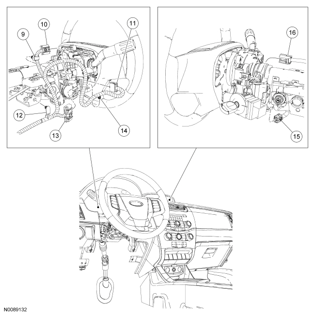
| 9 | — | Wiring harness retainer (part of 14401) |
| 10 | — | Multifunction switch electrical connector (part of 14401) |
| 11 | — | Clockspring electrical connector (part of 14401) |
| 12 | — | Wiring harness retainer (part of 14401) |
| 13 | — | Ignition switch electrical connector (part of 14401) |
| 14 | — | Wiring harness retainer (part of 14401) |
| 15 | — | Passive Anti-Theft System (PATS) transceiver electrical connector (part of 14401) |
| 16 | — | Steering wheel rotation sensor electrical connector (part of 14401) |
| Item | Part Number | Description |
|---|---|---|
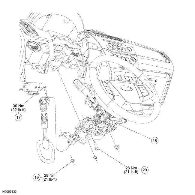
| 17 | W712882 | Upper steering column shaft-to-steering column bolt |
| 18 | 3C529 | Steering column |
| 19 | N806423 | Steering column nut (3 required) |
| 20 | W712250 | Steering column bolt |
Removal and Installation
All vehicles
- Remove the steering wheel. For additional information, refer to Steering Wheel in this section.
- Remove the steering column opening trim panel.
- Pull outward at the top of the trim panel to release the upper retainers.
- Carefully pull upward and outward on the bottom of the trim panel to release the lower retainers located at the bottom corners of the trim panel.
- Remove the bolt and position the hood release handle and cable aside.
- To install, tighten to 20 Nm (177 lb-in).
- Remove the 4 bolts and the steering column opening trim panel reinforcement.
- To install, tighten to 9 Nm (80 lb-in).
Vehicles with tilt steering column
- Release the steering column tilt lever.
All vehicles
- Remove the 3 screws and the upper and lower steering column shrouds.
- Press inward on the sides of the upper shroud and pull up to separate it from the lower shroud.
- Disconnect the Passive Anti-Theft System (PATS) transceiver, ignition switch, multifunction switch, steering wheel rotation sensor and clockspring electrical connectors.
- Detach the 3 wiring harness retainers from the steering column.
 WARNING: Do
not reuse steering column shaft bolts. This may result in fastener failure and steering column shaft detachment or loss of steering control. Failure to follow this instruction may result in serious injury to vehicle occupant(s).NOTICE: Do not allow the steering column to rotate while the steering column shaft is disconnected or damage to the clockspring may result. If there is evidence that the steering column has rotated, the clockspring must be removed and recentered. For additional information, refer to Section 501-20B.
Remove and discard the upper steering column shaft-to-steering column bolt and disconnect the upper steering column shaft from the steering column.- To install, tighten the new bolt to 30 Nm (22 lb-ft).
- Remove and discard the 3 steering column nuts.
- To install, tighten the new nuts to 28 Nm (21 lb-ft).
- Remove the steering column bolt and the steering column.
- To install, tighten to 28 Nm (21 lb-ft).
- WARNING: Do
not reuse steering column nuts. This may result in fastener failure and steering column detachment or loss of steering control. Failure to follow this instruction may result in serious injury to vehicle occupant(s).To install, reverse the removal procedure.
 Steering Column - Description and Operation
The steering column consists of the following:
Steering wheel
Steering column
Upper and lower steering column shafts
Steering column switches
The steering column is the mechanical li ...
 Steering Column Lock Module
Removal and Installation
Item
Part Number
Description
1
—
Ignition switch electrical connector (part of 14401)
2
—
Electrical harness pi ...
More about Ford Focus:
Ford Focus Valve Guide Inner Diameter
NOTE: Refer to the appropriate Section 303-01 for the specification.
NOTE: Valve guides tend to wear in an hourglass pattern. The ball
gauge can be inserted into the combustion chamber side of the valve guide, if
necessary.
Use a ball gauge to determine the inside diameter of the valv ...
Nissan Frontier - Instrument Panel - Keys - Brake system
