Ford Focus Service Manual: Subframe - Front

|
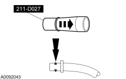
Installer Set, Teflon® Seal 211-D027 (D90P-3S17-A) or equivalent |

|
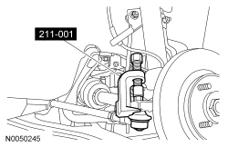
Remover, Tie-Rod End 211-001 (TOOL-3290-D) |
NOTE:
The front bumper cover and the RH/LH brake assemblies have been removed for clarity.
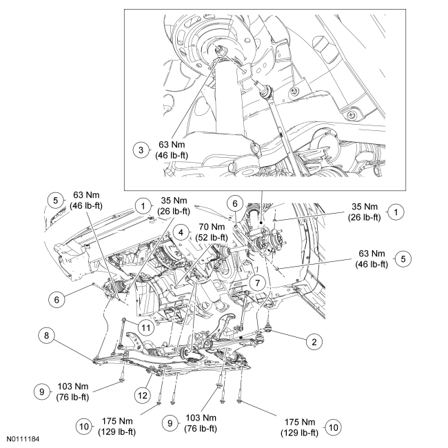
| Item | Part Number | Description |
|---|---|---|
| 1 | W520203 | Tie-rod end nuts (2 required) |
| 2 | 3A130 | Tie-rod end (2 required) |
| 3 | W713760 | Stabilizer bar link nut (2 required) |
| 4 | W702826 | Roll restrictor bolt |
| 5 | W520213 | Lower arm ball joint pinch nuts (2 required) |
| 6 | W711859 | Lower arm ball joint pinch bolts (2 required) |
| 7 | 3A238 | Lower arm ball joint heat shield (2 required) |
| 8 | 3078 | Lower arm ball joint (2 required) |
| 9 | W709634 | Subframe upper bolts (M12) (2 required) |
| 10 | W709634 | Subframe lower bolts (M14) (4 required) |
| 11 | — | Stabilizer link (2 required) |
| 12 | 5019 | Front subframe |
Removal
- Center the steering wheel, remove the ignition key and lock the steering wheel in position.
- Disconnect the steering column shaft from the steering column coupling shaft.
- Discard the bolt.
- Remove the front wheels and tires. For additional information, refer to Section 204-04.
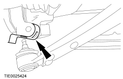
- NOTICE: Leave the tie-rod end nuts in place to protect the ball joint
studs or damage to the vehicle may occur.
Loosen the tie-rod end nut on both sides.
- Using the Tie-Rod End Remover, disconnect the tie-rod end from the wheel
knuckle on both sides.
- Remove and discard the tie-rod end nuts.
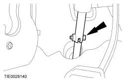
- Remove the stabilizer bar link nuts on both sides.
- Remove the engine support insulator-to-transaxle center bolt.
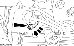
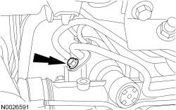
- Remove the power steering line retainer bolt from the steering gear.
- Remove the power steering lines bolt, rotate the power steering line clamp
clockwise, and disconnect the 2 power steering lines from the power steering
gear.
- Allow the remaining oil to drain into a suitable container.
- Discard the O-ring seals.
- Remove the roll restrictor bolt.
- Using a suitable support table, support the front subframe.
- Index-mark the location of the subframe to the vehicle before removal.
- NOTE:
Separate the ball joint from the wheel knuckle as the front subframe is lowered.
Disconnect the lower arm ball joint from the wheel knuckle on both sides.
- Remove the 2 lower arm ball joint heat shields.
- Remove the 6 subframe bolts.
- Remove the front subframe.
- If installing a new front subframe, transfer parts as necessary.
Installation
- Position the subframe to the vehicle.
- NOTE:
While tightening the subframe bolts, make sure the front subframe does not move.
Loosely install the 4 subframe lower bolts.
- Align the index marks made before removal.
- Tighten to 175 Nm (129 lb-ft).
- Install the 2 subframe upper bolts.
- Tighten to 103 Nm (76 lb-ft).
- Install the roll restrictor bolt.
- Tighten to 70 Nm (52 lb-ft).
- Remove the support table.
- NOTICE: Make sure the 2 lower arm ball joint heat shields are installed
to prevent damage to the ball joints.
Install the 2 heat shields (1 each side).
- Position the lower arm ball joint to the wheel knuckle on both sides and
install the bolts and nuts.
- Tighten to 63 Nm (46 lb-ft).
- NOTE:
New O-ring seals must be installed any time the lines are disconnected from the steering gear.
Using the Teflon® Seal Installer Set, install new O-ring seals (high-pressure hose pin, 3F886-AA, return hose pin 3F886-BA) onto the power steering lines.
- Connect the power steering lines to the power steering gear, rotate the
power steering line clamp counterclockwise and install the bolt.
- Tighten to 18 Nm (159 lb-in).
- Install the power steering line retainer bolt.
- Install the engine support insulator-to-transaxle center bolt.
- Tighten to 50 Nm (37 lb-ft).
- Install the 2 stabilizer bar links and the nuts.
- Tighten to 63Nm (46 lb-ft).
 WARNING: Do
not reuse a tie rod-to-wheel knuckle nut. This can result in nut failure and loss of steering control. Failure to follow this instruction may result in serious injury to vehicle occupant(s).Install the 2 tie-rod ends and the nuts.
- Tighten to 35 Nm (26 lb-ft).
- Install the front wheels and tires. For additional information, refer to Section 204-04.
- WARNING: Install
a new steering column shaft bolt. Reuse could result in bolt failure and loss of vehicle control. Failure to follow this instruction may result in serious injury to vehicle occupant(s).Connect the steering column shaft to the steering column coupling shaft and install the bolt.
- Tighten to 28 Nm (21 lb-ft).
- Fill and bleed the power steering system. For additional information, refer to Section 211-00.
- Check the front end alignment and adjust as necessary. For additional information, refer to Section 204-00.
 Subframes
...
 Subframe - Rear
Item
Part Number
Description
1
W709634-S439
Crossmember bolts (6 required)
2
5K067
Crossmember
3
W500744
Front lower arm inbo ...
More about Ford Focus:
Ford Focus Washer Pump and Reservoir
Material
Item
Specification
Premium Quality Windshield Washer Fluid (Canada)
CXC-37-(A, B, D, and F) (Canada)
—
Premium Windshield Washer Concentrate (US)
ZC-32-A or B (US)
WSB-M8B16-A2
Removal and Installation
Remove the washer fluid re ...
Nissan Frontier - Instrument Panel - Keys - Brake system
