Ford Focus Service Manual: Transaxle Description
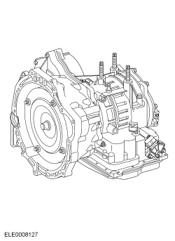
The 4F27E is a fully automatic, electronically controlled 4-speed transaxle designed for Front Wheel Drive (FWD) vehicles.
Its abbreviated designation 4F27E means:
- 4 — 4-speed transmission
- F — FWD
- 27 — originally designed for maximum input torque after torque converter: 365 Nm (270 lb-ft)
- E — fully electronically controlled
The individual ratios are achieved through 2 planetary gear sets, connected one
behind the other.
The individual components of the planetary gear sets are driven or held by means of 3 multi-plate clutches, a multi-plate brake, a brake band and a roller One-Way Clutch (OWC) .
The torque is transmitted to the final drive assembly through an intermediate gear stage.
The selector lever gives the driver a choice of P, R, N, D and L.
With the selector lever in the D position, it is possible to operate an Overdrive (O/D) switch on the selector lever to prevent the transaxle from shifting into 4th gear. The default gear for this transaxle is 3rd gear.
To minimize fuel consumption, the torque converter lock-up clutch is closed by the PCM in 3rd and 4th gears depending on the throttle position and vehicle speed.
The transaxle has electronic synchronous shift control, which guarantees extremely smooth gear shifting over the entire life of the transaxle.
A hydraulic emergency operating program maintains limited operation in the event of failure of important electrical components.
The transaxle can be tested using a scan tool through the Data Link Connector (DLC) in the passenger compartment.
| Gear Ratio (Typical shown, ratios are model dependent) | |
|---|---|
| 1st | 2.816:1 |
| 2nd | 1.498:1 |
| 3rd | 1.000:1 |
| 4th | 0.726:1 |
| Reverse | 2.649:1 |
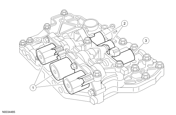
Valve Body
| Item | Part Number | Description |
|---|---|---|
| 1 | 7G484 | Pulse-Width Modulation (PWM) solenoid valves |
| 2 | 7H148 | Shift solenoid (on/off) valves |
| 3 | 7G353 | Main regulating valve Variable Force Solenoid (VFS) |
The valve body contains 6 solenoid valves:
- Three Pulse-Width Modulation (PWM) solenoid valves
- Two shift solenoid (on/off) valves
- One main regulating valve, Variable Force Solenoid (VFS)
The individual clutches and bands are supplied pressure from the PWM solenoid valves and the shift solenoid (on/off) valves and thus the gears are shifted.
The PWM solenoid valves allow direct actuation of the clutches and bands to make sure of extremely smooth shifting through precise pressure regulation.
The shift solenoid (on/off) valves switch the hydraulic path to the clutches and bands, reducing the number of required modulating valves.
The main regulating valve, VFS makes sure that sufficient hydraulic pressure is available in all operating conditions.
Pulse-Width Modulation (PWM) Solenoid Valves 1-3
PWM solenoid valves 1, 2 and 3 control the pressure to the bands and clutches.
Shift Solenoid (On/Off) Valves 1 and 2
The shift solenoid (on/off) valves switch the different oil passages in the valve body to direct the pressure to the individual clutches and bands.
The use of the shift solenoid valves are needed for direct actuation of the individual clutches and bands.
Main Regulating Valve
The main regulating valve, VFS controls the required main line pressure for the individual transmission ranges.
The main line pressure is controlled dependent on the current engine load.
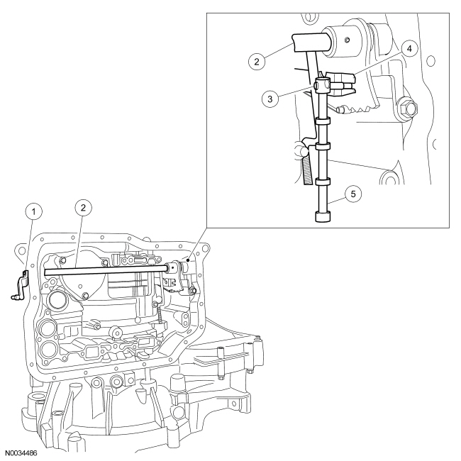
Internal Shift Mechanism
| Item | Part Number | Description |
|---|---|---|
| 1 | 7A256 | Manual control lever |
| 2 | 7C493 | Manual control shaft |
| 3 | — | Parking pawl engaging lever |
| 4 | 7E160 | Lever and bracket manual control assembly |
| 5 | — | Manual control valve (in valve body, which is not shown) |
The manual control lever is secured on a square on the manual control shaft. Axial movement of the selector lever cable is changed into rotation of the manual shaft.
In the transaxle, the manual control shaft operates the parking pawl engaging lever and the manual control lever of the manual control valve.
The manual control valve, a valve operated entirely manually, is moved by means of the manual control lever in the valve body.
The manual control valve guarantees the functions during hydraulic emergency operation.
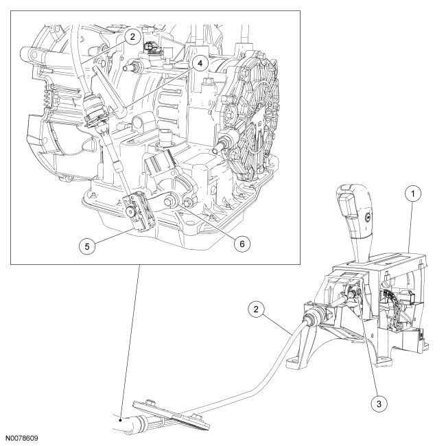
External Selector Lever Mechanism
| Item | Description |
|---|---|
| 1 | Selector lever assembly |
| 2 | Selector lever cable |
| 3 | Ball stud (part of 7E395) |
| 4 | Selector lever cable bracket |
| 5 | Manual control lever |
| 6 | Selector lever cable end (part of 7E395) |
The transaxle end of the selector lever cable is attached to a ball stud on the manual control lever.
The selector lever cable abutments are secured to the transaxle housing, and to the bracket of the selector lever.
The adjuster for the selector lever cable is located on the selector lever cable end on the transaxle side.
At the selector lever end, the selector lever cable is clipped onto a ball stud.
Intermediate Gear Stage and Final Drive Assembly
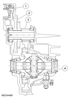
| Item | Description |
|---|---|
| 1 | Final drive input gear |
| 2 | Transfer shaft input gear |
| 3 | Transfer shaft output gear |
| 4 | Differential |
The final drive input gear is splined to the planet carrier of the front planetary gear set and drives the transfer shaft input gear of the intermediate gear stage.
The transfer shaft output gear of the intermediate gear stage drives the final drive assembly.
The torque is transmitted to the halfshafts through the final drive assembly.
The differential offsets differences in speed of rotation of the halfshafts.
The intermediate gear stage is designed so that the final drive ratio can be adapted to requirements when the automatic transaxle is used in conjunction with different engines.
 Transaxle - Removal (Automatic Transaxle/Transmission — 4F27E)
Special Tool(s)
Adapter for 303-290A
303-290-01
Adapter for 303-290A (Support Leg)
303-290-03A
Retainer, Torque Converter
3 ...
 Transaxle Draining and Filling
Material
Item
Specification
Motorcraft® Full Synthetic Manual Transmission Fluid
XT-M5-QS
WSD-M2C200-C
With the vehicle in NEUTRAL, position it on a hoist. Fo ...
More about Ford Focus:
Ford Focus Window Glass - Front Door
Material
Item
Specification
Seam Sealer
TA-2
—
Removal and Installation
Remove the front door speaker. For additional information, refer to Section
415-00.
NOTE: Do not touch the adhesive surface during removal or installation
of the wa ...
Nissan Frontier - Instrument Panel - Keys - Brake system
