Ford Focus Service Manual: Transaxle Electronic Control System
Overview Transmission Control
| Item | Description |
|---|---|
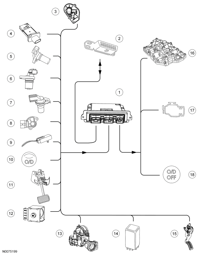
| 1 | PCM |
| 2 | Data Link Connector (DLC) |
| 3 | Throttle Position (TP) sensor |
| 4 | Mass Air Flow (MAF) and Intake Air Temperature (IAT) sensors |
| 5 | Crankshaft Position (CKP) sensor |
| 6 | Output Shaft Speed (OSS) sensor |
| 7 | Turbine Shaft Speed (TSS) sensor |
| 8 | Transmission Range (TR) sensor |
| 9 | Transmission Fluid Temperature (TFT) sensor |
| 10 | Overdrive (O/D) switch |
| 11 | Brake Pedal Position (BPP) switch |
| 12 | Brake Shift Interlock Actuator (BSIA) |
| 13 | Ignition key lock solenoid |
| 14 | A/C relay |
| 15 | Accelerator Pedal Position (APP) sensor |
| 16 | Solenoid valves in the valve body |
| 17 | Powertrain warning indicator in Instrument Cluster (IC) |
| 18 | O/D indicator in IC |
The PCM and its input/output network controls the following operations:
- Shift timing
- Line pressure (shift feel)
- Torque Converter Clutch (TCC)
The transaxle control is separate from the engine control strategy in the PCM, although some of the input signals are shared. When determining the best operating strategy for transaxle operation, the PCM uses input information from certain engine-related and driver-demand related sensors and switches.
In addition, the PCM receives input signals from certain transaxle-related sensors and switches. The PCM also uses these signals when determining transaxle operating strategy.
Using all of these input signals, the PCM can determine when the time and conditions are right for a shift, or when to apply or release the TCC . It will also determine the best line pressure needed to optimize shift feel. To accomplish this, the PCM uses output solenoids to control transaxle operation.
Electronic Synchronous Shift Control
Control of Shift Operations
During a shift operation, certain elements are released while others are actuated. Ideally, this process takes place simultaneously (synchronously) to avoid jerky gear shifting.
The time for the shift operation should remain within the time limits provided.
When the shift operation is controlled conventionally, the pressure buildup and reduction at the shift elements are set and defined for ideal conditions (synchronous shifting).
As there is no way of influencing the control in the event of different levels of wear in the shift elements, when the transaxle has been used for a fairly high mileage, it is possible that the pressure buildup and reduction may no longer be synchronous.
The result or premature pressure reduction at the element to be switched off is an unwanted rise in the Turbine Shaft Speed (TSS) as the element to be switched on cannot transmit the input torque.
The result of delayed pressure reduction at the element to be switched off is an unwanted decrease in the TSS as both shift elements transmit the input torque. In the process the torque is transmitted to the transaxle housing through internal locking.
In both cases, a jerk will be felt during the shift operation.
In addition, wear in the shift elements leads to a lengthening of the shift operation. Therefore, shifting takes longer when the transaxle has accumulated a higher mileage.
Control of Shift Operations With Electronic Synchronous Shift Control
In the automatic transaxle, electronic synchronous shift control is used.
Electronic synchronous shift control monitors the shift operations and is able to adapt to the wear in the shift elements over the life of the transaxle.
This is possible since the shift elements are actuated by modulating valves.
The system monitors the shift time whether the shift operation is synchronous.
If the PCM detects a deviation from the stored values for the shift time and synchronization of the shift operation, the pressure buildup or reduction is adapted accordingly.
Emergency Operating Program
If correct gear shifting can no longer be guaranteed due to failure of certain signals, the PCM changes to an emergency operating program.
The driver is informed of the operation of the emergency operating program by the illumination of the powertrain warning indicator in the Instrument Cluster (IC) .
Continued motoring is guaranteed in the following limited conditions:
- Maximum main line pressure
- Third gear in selector lever positions D and L without the TCC
- Reverse gear in selector lever position R
Throttle Position (TP) Sensor Sensor
The Throttle Position (TP) sensor is located on the Throttle Body (TB) .
It supplies the PCM with information about the position of the throttle plate.
It also detects the speed of actuation of the throttle plate.
The PCM uses the signals for the following functions among other things:
- to determine the shift timing.
- to control the main line pressure.
- to control the TCC .
- for kickdown.
In case of absence of the TP signal, the engine control uses the signals of the Mass Air Flow (MAF) and Intake Air Temperature (IAT) sensors as a substitute signal. The main line pressure is increased and hard shifts may occur.
Accelerator Pedal Position (APP) Sensor
The Accelerator Pedal Position (APP) sensor is mounted on the accelerator pedal. The APP detects the position of the accelerator pedal and inputs this information as a voltage to the PCM. The PCM uses APP sensor information to aid in determining line pressure, shift scheduling and TCC operation. Failure of this sensor will cause the transaxle to operate at higher line pressure to avoid damage to the transaxle. This higher line pressure causes harsh upshifts and harsh engagements.
Mass Air Flow (MAF) and Intake Air Temperature (IAT)
The MAF sensor is located between the air cleaner housing and the air intake hose leading to the throttle housing.
The IAT sensor is incorporated in the housing of the MAF sensor.
The MAF sensor in conjunction with the IAT sensor provides the PCM with the primary load signal.
The PCM uses the signals for the following functions among other things:
- to control the shift operations.
- to control the main line pressure.
If the MAF sensor fails, the signal of the TP sensor is used as a substitute.
Crankshaft Position (CKP) Sensor
The Crankshaft Position (CKP) sensor is located on the engine/transaxle flange.
The CKP sensor is an inductive sensor which provides the PCM with information about the engine speed and position of the crankshaft.
The signal is used for the following functions among other things:
- to control the TCC .
- to check the torque converter slip.
- to control the main line pressure.
No substitute signal is available for the CKP sensor. If the signal is not present, the engine stops.
Turbine Shaft Speed (TSS) Sensor
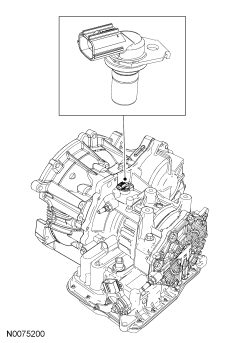
The TSS sensor is located in the transaxle housing over the transaxle input shaft.
The TSS sensor is an inductive sensor which senses the speed of rotation of the transaxle input shaft.
The signal is used for the following functions:
- to control the shift operations.
- to control the TCC .
- to check the torque converter slip.
If the TSS sensor fails, the signal of the Output Shaft Speed (OSS) sensor is used as a substitute signal.
Output Shaft Speed (OSS) Sensor
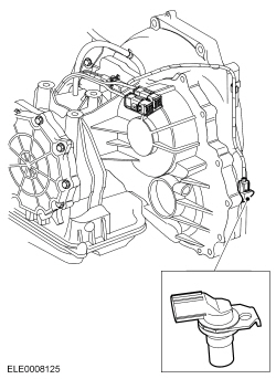
The OSS sensor is located in the transaxle housing above the rotor in the differential.
The OSS sensor is an inductive sensor which detects the vehicle speed by means of a rotor on the differential.
The signal is used for the following functions among other things:
- to determine the shift timing.
- to supply the vehicle speed input signal for the PCM.
If the OSS sensor fails, the signal of the TSS sensor is used as a substitute signal.
Transmission Range (TR) Sensor
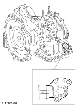
The Transmission Range (TR) sensor is located on the manual shaft on the transaxle
housing.
When the manual control shaft is moved by means of the selector lever cable, an engagement pin in the inner ring of the TR sensor moves through the different positions. The signals are transmitted to the PCM, the reversing lamps and the starter inhibitor relay.
NOTE:
Correct operation of the TR sensor is only guaranteed when the manual selector lever cable is adjusted correctly.
The signals of the TR sensor are used for the following functions:
- to recognize the selector lever position.
- to actuate the starter inhibitor relay.
- to actuate the reversing lamps.
No substitute signal is available for the TR sensor.
If the connection is cut, the vehicle cannot be started.
Brake Pedal Position (BPP)
The Brake Pedal Position (BPP) switch is mounted on the brake pedal bracket.
It switches the stoplights on and tells the PCM when the brakes are applied.
The signal of the BPP switch is used by the PCM for the following functions:
- to release the TCC when the brake pedal is pressed.
- to switch off the selector lever Brake Shift Interlock Actuator (BSIA) when the brake pedal is pressed in PARK.
No substitute signal is available for the BPP switch.
If the connection to the BPP switch is cut, the selector lever cannot be moved out of PARK.
Translation Fluid (TFT) Sensor
The Transmission Fluid Temperature (TFT) sensor is located on the internal wiring harness to the solenoid valves in the transmission fluid pan.
It is a resistor and measures the TFT .
The TFT is used by the PCM for the following functions:
- Applying the TCC is not permitted until the transmission fluid reaches a certain temperature.
- Engagement of 4th gear is prevented in extreme sub-zero temperatures until the normal operating temperature is reached.
- If the TFT is excessive, a pre-set fixed shift curve is selected and the TCC is closed in 2, 3 and 4, and the transaxle warning indicator is activated. No substitute signal is available for the TFT sensor.
Overdrive (O/D) Switch
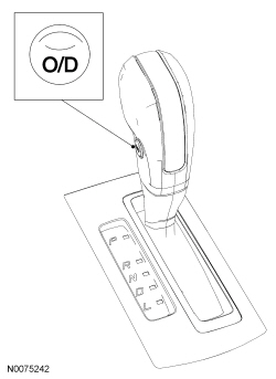
The Overdrive (O/D) switch transmits a signal to the PCM to select or suppress 4th
gear in selector lever position D.
The signal of the O/D switch is used for the following functions:
- as an input signal to convey the driver's intent to the PCM.
- to display the driver's intent with the O/D indicator in the Instrument Cluster (IC) .
No substitute signal is available for the O/D switch. If it should fail, it is always possible to shift into 4th gear in selector lever position D.
Brake Shift Interlock Actuator (BSIA)
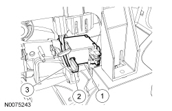
| Item | Description |
|---|---|
| 1 | Actuator |
| 2 | Blocker |
| 3 | Manual release mechanism |
When the ignition is switched to the ON or RUN position, the BSIA is actuated by pressing the brake (signal from the BPP switch). This retracts the blocker so that the selector lever can be moved out of PARK.
Substitute Park Release
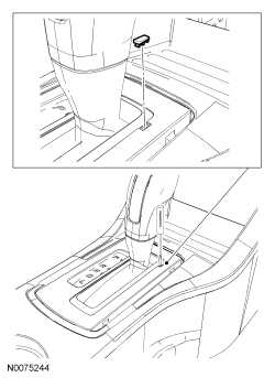
NOTE:
If PARK is selected again, the selector lever is locked again.
If the brake signal should fail due to a malfunction, manual unlocking of the selector lever is possible.
For this, the cover of the release mechanism must be removed and a suitable tool pressed into the opening until the selector lever can be moved out of PARK.
A/C
If the PCM registers a kickdown signal Wide Open Throttle (WOT) and the throttle plate is opened 95%, the A/C is switched off for a maximum of 15 seconds.
Starter Inhibitor Relay
The relay prevents the engine starting in selector lever positions R, D and L.
The relay obtains the information about the position of the selector lever directly from the TR sensor.
Ignition Key Lock Solenoid
The solenoid is incorporated in the ignition lock. In selector lever position P, the ground connection to the solenoid is cut. The locking pin does not engage in the ignition lock.
In all the other selector lever positions, the ground connection to the solenoid is closed and the locking pin engages in the ignition lock.
When the selector lever is not in position P, removal of the ignition key is prevented.
Overdrive (O/D) Indicator
The O/D indicator is located in the IC and is colored green.
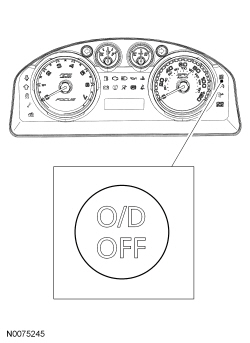
It tells the driver that shifting into 4th gear is prevented by the transaxle control.
The O/D light flashes to tell the driver that the transaxle control has switched to the emergency operating program or that the TFT is too high.

 Brake Shift Interlock Override
NOTE: If it is necessary to use the brake shift interlock override
procedure to move the selector lever out of the PARK position, it is possible that
a fuse has blown and the brake lights are not ...
More about Ford Focus:
Ford Focus Generic OBD PID List
An X in the Freeze Frame column denotes both a mode 1 and mode 2 PID (real time
and freeze frame).
Freeze Frame
Acronym
Description
Measurement Units
X
APP_D
Accelerator Pedal Position D
%
X
APP_E
Accelerator Pedal Position E
%
X
...
Nissan Frontier - Instrument Panel - Keys - Brake system
