Ford Focus Service Manual: Clockspring
| Item | Part Number | Description |
|---|---|---|
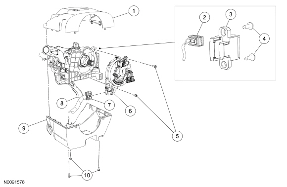
| 1 | 3530 | Upper steering column shroud |
| 2 | — | Steering wheel rotation sensor electrical connector (if equipped) (part of 14401) |
| 3 | 3F818 | Steering wheel rotation sensor (if equipped) |
| 4 | — | Steering wheel rotation sensor screws (if equipped) (2 required) |
| 5 | W506942 | Clockspring screws (2 required) |
| 6 | 14A644 | Clockspring |
| 7 | — | Clockspring electrical connector (part of 14401) |
| 8 | — | Steering column tilt lock/ unlock handle |
| 9 | 3K512 | Lower steering column shroud |
| 10 | — | Lower steering column shroud screws (3 required) (part of 3K512) |
Removal
NOTE:
The air bag warning indicator illuminates when the correct Restraints Control Module (RCM) fuse is removed and the ignition is ON.
NOTE:
The Supplemental Restraint System (SRS) must be fully operational and free of faults before releasing the vehicle to the customer.
- Remove the driver air bag module. For additional information, refer to Driver Airbag in this section.
- Tilt the steering wheel to the lowest position and lock the tilt handle.
- NOTICE: To prevent damage to the clockspring, make sure the road wheels
are in the straight-ahead position.
Remove the steering wheel. For additional information, refer to Section 211-04.
- Release the tabs and remove the upper steering column shroud.
- Remove the 3 lower steering column shroud screws, release the tilt column locking lever and remove the lower steering column shroud.
- Disconnect the clockspring electrical connector.
- If equipped, remove the 2 screws and position aside the steering wheel rotation sensor.
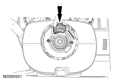
- Remove the 2 screws and clockspring.
Installation
- NOTICE: If installing a new clockspring, do not remove the clockspring
anti-rotation key until the steering wheel is installed. If the anti-rotation
key has been removed before installing the steering wheel, the clockspring must
be centered. Failure to follow this instruction may result in component damage
and/or system failure.
Install the clockspring and 2 screws.
- Connect the clockspring electrical connector.
- If equipped, install the steering wheel rotation sensor and 2 screws.
- Install the lower steering column shroud and 3 screws.
- Attach the upper steering column shroud to the lower steering column shroud.
 WARNING: If
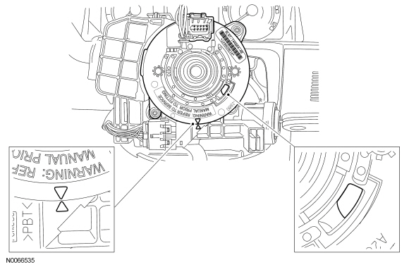
the clockspring is not correctly centralized, it may fail prematurely. If in doubt, repeat the centralizing procedure. Failure to follow these instructions may increase the risk of serious personal injury or death in a crash.If a new clockspring was installed and the anti-rotation key has not been removed, proceed to Step 8
. If a new clockspring was installed and the anti-rotation key has been removed before the steering wheel is installed or the same clockspring is being installed, rotate the clockspring inner rotor counterclockwise
and carefully feel for the ribbon wire to run out of length with slight resistance. Stop rotating the clockspring inner rotor at this point.
- Starting with the clockspring inner rotor, wiring and connector in the 12
o'clock position, rotate the inner rotor clockwise
through 4 revolutions to center the clockspring. Verify that the clockspring is correctly centered by observing that after 4 revolutions:
- the clockspring rotor window is in the 4 o'clock position and the yellow indicator shows in the window.
- the 2 arrows located on the inner and outer rotor of the clockspring line up in the 6 o'clock position.
- the clockspring inner rotor, wiring and connector are in the 12 o'clock position.
- NOTICE: To prevent damage to the clockspring, make sure the road wheels
are in the straight-ahead position.
NOTE:
The clockspring inner rotor, wiring and connector must be in the 12 o'clock position to install the steering wheel.
Install the steering wheel. For additional information, refer to Section 211-04.
- If a new clockspring was installed, remove the anti-rotation key.
- Install the driver air bag module. For additional information, refer to Driver Airbag in this section.
 Side Air Curtain
NOTE: Two-door shown, 4-door similar.
Item
Part Number
Description
1
042D94
Side air curtain module
2
—
Side air curtain module front teth ...

More about Ford Focus:
Ford Focus Technical specifications
Vehicle fluids
1 Providing it meets the specification defined by WSS-M2C913-C, you can also
use
Ford Engine Oil or an alternative engine oil.
2 On vehicles with a 2.5L Duratec-RS engine, use only this oil.
Topping up the oil: If you are unable to find an oil that meets the
specification ...
