Ford Focus Service Manual: Crankshaft Pulley

|
Alignment Plate, Camshaft 303-465 (T94P-6256-CH) |

|
Holding Tool, Crankshaft Damper 303-1416 |

|
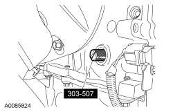
Timing Peg, Crankshaft TDC 303-507 |
| 6 mm x 18 mm bolt |
| Item | Specification |
|---|---|
| Motorcraft® SAE 5W-20 Premium Synthetic Blend Motor Oil (US); Motorcraft® SAE 5W-20 Super Premium Motor Oil (Canada) XO-5W20-QSP (US); CXO-5W20-LSP12 (Canada) | WSS-M2C945-A |
Removal
NOTICE: Do not loosen or remove the crankshaft pulley bolt without first installing the special tools as instructed in this procedure. The crankshaft pulley and the crankshaft timing sprocket are not keyed to the crankshaft. The crankshaft, the crankshaft sprocket and the pulley are fitted together by friction, using diamond washers between the flange faces on each part. For that reason, the crankshaft sprocket is also unfastened if the pulley bolt is loosened. Before any repair requiring loosening or removal of the crankshaft pulley bolt, the crankshaft and camshafts must be locked in place by the special service tools, otherwise severe engine damage can occur.
NOTICE: During engine repair procedures, cleanliness is extremely important. Any foreign material, including any material created while cleaning gasket surfaces, that enters the oil passages, coolant passages or the oil pan can cause engine failure.
- With the vehicle in NEUTRAL, position it on a hoist. For additional information, refer to Section 100-02.
- Remove the RH wheel and tire. For additional information, refer to Section 204-04.
- Remove the accessory drive belt. For additional information, refer to Section 303-05.
- Remove the valve cover. For additional information, refer to Valve Cover in this section.
- NOTICE: Failure to position the No. 1 piston at Top Dead Center (TDC)
can result in damage to the engine. Turn the engine in the normal direction
of rotation only.
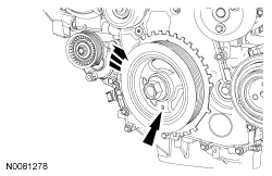
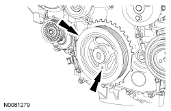
Using the crankshaft pulley bolt, turn the crankshaft clockwise to position the No. 1 piston at Top Dead Center (TDC) .
- The hole in the crankshaft pulley should be in the 6 o'clock position.
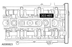
- NOTICE: The Camshaft Alignment Plate is for camshaft alignment only.
Using this tool to prevent engine rotation can result in engine damage.
NOTE:
The camshaft timing slots are offset. If the Camshaft Alignment Plate cannot be installed, rotate the crankshaft one complete revolution clockwise to correctly position the camshafts.
Install the Camshaft Alignment Plate in the slots on the rear of both camshafts.
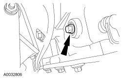
- Remove the engine plug bolt.
- NOTE:
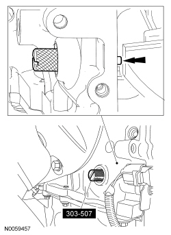
The Crankshaft TDC Timing Peg will contact the crankshaft and prevent it from turning past TDC . However, the crankshaft can still be rotated in the counterclockwise direction. The crankshaft must remain at the TDC position during the crankshaft pulley removal and installation.
Install the Crankshaft TDC Timing Peg.
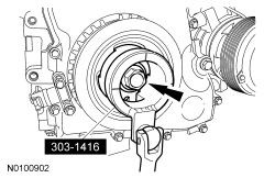
- NOTICE: The crankshaft must remain in the Top Dead Center (TDC) position
during removal of the pulley bolt or damage to the engine can occur. Therefore,
the crankshaft pulley must be held in place with the Crankshaft Damper Holding
Tool, and the bolt should be removed using an air impact wrench (1/2-in drive
minimum).
NOTICE: The crankshaft sprocket diamond washer may come off with the crankshaft pulley. The diamond washer must be replaced. Remove and discard the diamond washer. If the diamond washer is not installed, engine damage may occur.
Use the Crankshaft Damper Holding Tool and a suitable 1/2-in drive hand tool to hold the crankshaft pulley. Use an air impact wrench to remove the crankshaft pulley bolt.- Remove and discard the crankshaft pulley bolt and washer.
- Remove the crankshaft pulley.
- Remove the diamond washer and discard.
Installation
- Install a new diamond washer.
- NOTE:
Do not install the crankshaft pulley bolt at this time.
NOTE:
Apply clean engine oil on the seal area before installing.
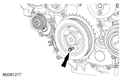
Position the crankshaft pulley onto the crankshaft with the hole in the pulley at the 6 o'clock position.
- NOTICE: Only hand-tighten the 6 mm bolt or damage to the front cover
can occur.
NOTE:
This step will correctly align the crankshaft pulley to the crankshaft.
Install a standard 6 mm x 18 mm bolt through the crankshaft pulley and thread it into the front cover.
- NOTICE: The crankshaft must remain in the Top Dead Center (TDC) position
during installation of the pulley bolt or damage to the engine can occur. Therefore,
the crankshaft pulley must be held in place with the Crankshaft Damper Holding
Tool and the bolt should be installed using hand tools only.
NOTE:
Do not reuse the crankshaft pulley bolt.
Install a new crankshaft pulley bolt. Use the Crankshaft Damper Holding Tool and a suitable 1/2-in drive hand tool to hold the crankshaft pulley, tighten the crankshaft pulley bolt in 2 stages:- Stage 1: Tighten to 100 Nm (74 lb-ft).
- Stage 2: Tighten an additional 90 degrees (one-fourth turn).
- Remove the 6 mm x 18 mm bolt.
- Remove the Crankshaft TDC Timing Peg.
- Remove the Camshaft Alignment Plate.
- NOTE:
Only turn the engine in the normal direction of rotation.
Turn the crankshaft clockwise one and three-fourths turns.
- Install the Crankshaft TDC Timing Peg.
- NOTE:
Only turn the engine in the normal direction of rotation.
Turn the crankshaft clockwise until the crankshaft contacts the Crankshaft TDC Timing Peg.
- NOTICE: Only hand-tighten the bolt or damage to the front cover can occur.
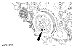
Using the 6 mm x 18 mm bolt, check the position of the crankshaft pulley.
- If it is not possible to install the bolt, the engine valve timing must be corrected by repeating this procedure.
- Install the Camshaft Alignment Plate to check the position of the camshafts.
- If it is not possible to install the Camshaft Alignment Plate, the engine valve timing must be corrected by repeating this procedure.
- Remove the Camshaft Alignment Plate.
- Remove the 6 mm x 18 mm bolt.
- Remove the Crankshaft TDC Timing Peg.
- Install the engine plug bolt.
- Tighten to 20 Nm (177 lb-in).
- Install the valve cover. For additional information, refer to Valve Cover in this section.
- Install the accessory drive belt. For additional information, refer to Section 303-05.
- Install the RF wheel and tire. For additional information, refer to Section 204-04.
 Accessory Drive
The accessory drive:
has a single serpentine drive belt with 6 ribs.
has automatic tensioning.
is not adjustable.
The accessory drive system provides power to operate components which p ...
 Accessory Drive Belt Tensioner
Removal and Installation
With the vehicle in NEUTRAL, position it on a hoist. For additional information,
refer to Section 100-02.
Remove the 2 bolts and accessory drive belt spla ...
More about Ford Focus:
Ford Focus Using a USB device
Various icons are used to identify types
of audio file, folders etc.
USB device is the active source
Folder
Playlist
Album
Artist
Filename
Track title
Information not available
Sony radio
Operation
Select the USB device as the audio
source by repeatedly p ...
Nissan Frontier - Instrument Panel - Keys - Brake system
