Ford Focus Service Manual: Engine - Automatic Transaxle - Engine - 2.0L

|
2,200# Floor Crane, Fold Away 300-OTC1819E or equivalent |

|
Lifting Bracket, Engine 303-050 (T70P-6000) |

|
Powertrain Lift 300-OTC1585AE or equivalent |

|
Retainer, Torque Converter 307-346 (T97T-7902-A) |

|
Spreader Bar 303-D089 (D93P-6001-A3) or equivalent |

|
Adjustable Grip Arm, 1735A 014-00001 or equivalent |
- With the vehicle in NEUTRAL, position it on a hoist. For additional information, refer to Section 100-02.
- Release the fuel system pressure. For additional information, refer to Section 310-00.
- Recover the A/C system. For additional information, refer to Section 412-00.
- Remove the Air Cleaner (ACL) and ACL outlet pipe. For additional information, refer to Section 303-12.
- Disconnect the crankcase vent tube from the valve cover.
- Remove the battery tray. For additional information, refer to Section 414-01.
- Disconnect the positive battery cable nut.
- Detach the 2 positive battery cable wire harness retainer.
- Remove the bolt and the negative battery cable ground.
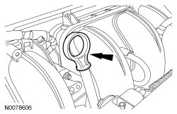
- Disconnect the fuel tube quick connect coupling from the fuel rail. For additional information, refer to Section 310-00.
- Disconnect the Evaporative Emission (EVAP) and position aside. For additional information, refer to Section 310-00.
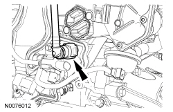
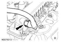
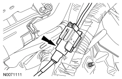
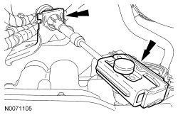
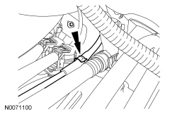
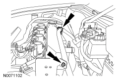
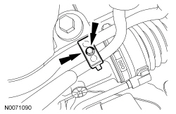
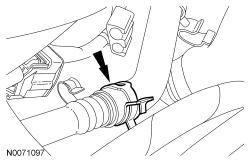
- Disconnect the power brake booster vacuum tube.
- Depress the quick connect locking ring.
- Pull the vacuum tube out of the quick connect fitting.
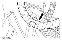
- Detach the brake booster vacuum hose retainer.
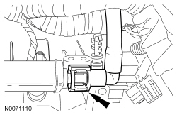
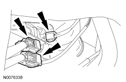
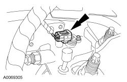
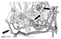
- Detach and disconnect the 2 engine harness electrical connectors.
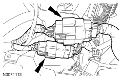
- Detach the engine harness from the coolant outlet bracket harness retainer.
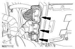
- Disconnect the 3 PCM electrical connectors.
- Disconnect the starter wire harness electrical connector.
- Disconnect the Heated Oxygen Sensor (HO2S) and Catalyst Monitor Sensor (CMS) electrical connectors and detach the wire harness retainer.
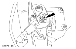
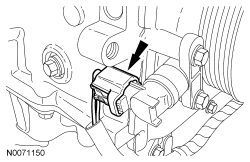
- Disconnect the transaxle shift cable from the lever and bracket.
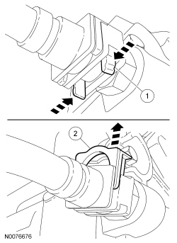
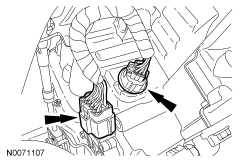
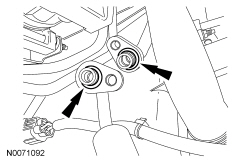
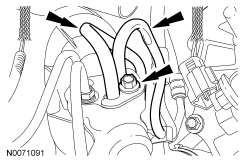
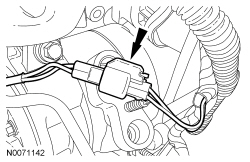
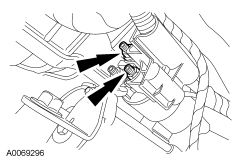
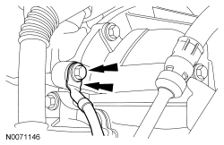
- Remove the transmission fluid cooler tube secondary latches.
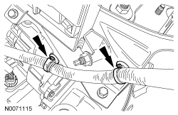
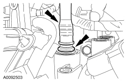
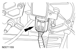
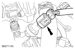
- NOTE:
Transaxle fluid cooler inlet tube shown, transaxle fluid cooler outlet tube similar.
Disconnect the 2 transaxle fluid cooler tubes from the transaxle.
- Squeeze the tabs together.
- Slide the transaxle fluid cooler tube lock up and remove the transaxle fluid cooler tubes from the transaxle.
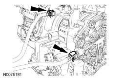
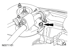
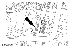
- Disconnect the 2 transaxle electrical connectors.
- Detach the shift cable from the retainer.
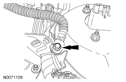
- Remove the engine oil level indicator.
- Remove the bolt and the radio capacitor ground cable.
- Remove the 2 front wheels and tires. For additional information, refer to Section 204-04.
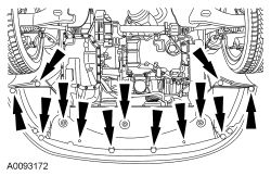
- Remove the retainers and the splash shield.
- Remove the accessory drive belt and tensioner. For additional information, refer to Section 303-05.
- Remove the generator. For additional information, refer to Section 414-00.
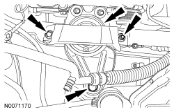
- Detach the 4 B+ battery cable wire harness retainers (2 shown) and position aside.
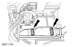
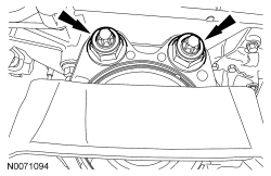
- Remove the 2 A/C tube nuts.
- Remove the nut and the A/C tube bracket from the A/C compressor stud bolt.
- Disconnect the A/C tubes from the compressor.
- Discard the 2 O-ring seals.
- Drain the engine cooling system. For additional information, refer to Section 303-03.
- Remove the cooling fan motor and shroud. For additional information, refer to Section 303-03.
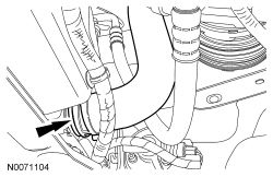
- Disconnect the lower radiator hose from the radiator.
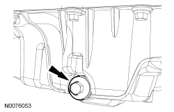
- Drain the engine oil.
- Install the drain plug and tighten to 28 Nm (21 lb-ft).
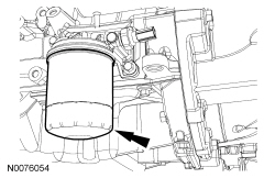
- Remove the engine oil filter and discard.
- Remove the LH halfshaft. For additional information, refer to Section 205-04.
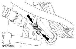
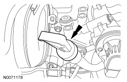
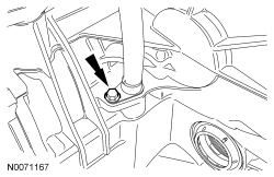
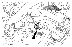
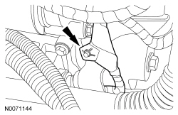
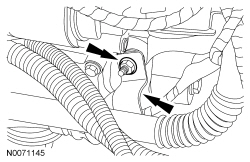
- Remove the bolt and the power steering tube clip.
- Remove the bolt and the power steering tubes from the steering gear.
- Discard the 2 power steering tube O-ring seals.
- Remove the 2 nuts and disconnect the flexpipe from the muffler and tailpipe
assembly.
- Remove and discard the nuts and gasket.
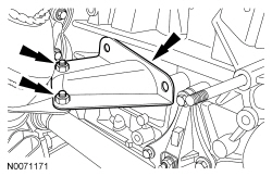
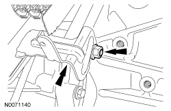
- Remove the 2 catalytic converter support bracket-to-engine bolts.
- Remove the 2 bolts and the catalytic converter support bracket.
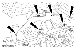
- NOTE:
Mark the location of bolts for installation.
Remove the 6 bolts and the catalytic converter heat shield.
- Remove and discard the 7 catalytic converter-to-engine nuts.
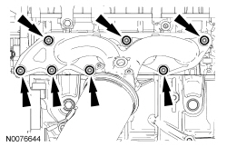
- Position aside the catalytic converter and support with mechanic's wire.
- Remove and discard the catalytic converter gasket.
- Remove the power steering pump. For additional information, refer to Section 211-02.
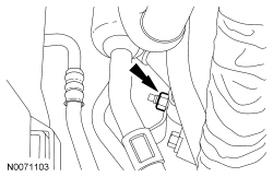
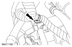
- Disconnect the upper radiator hose, the heater hose from the coolant bypass.
- Disconnect the heater hose from the coolant tube.
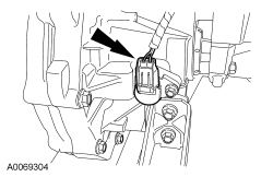
- Disconnect the throttle control electrical connector.
- Remove the transaxle fluid level indicator.
- Detach the wire harness retainer from the transaxle fluid indicator tube.
- Remove the transaxle fluid indicator tube bolt.
- Remove the transaxle fluid indicator tube bracket bolt and the transaxle fluid indicator tube.
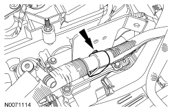
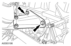
- NOTE:
The bolts are different lengths, mark the bolts for installation.
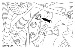
Remove the 2 bolts and the transaxle roll restrictor.
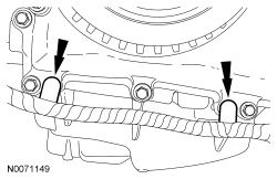
- Remove the 2 lower bellhousing-to-oil pan bolts.
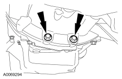
- Remove the 2 oil pan-to-bellhousing bolts.
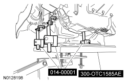
- Using the Powertrain Lift and Adjustable Grip Arm, secure the engine to the lift table.
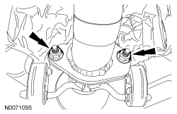
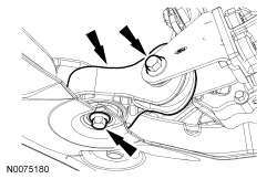
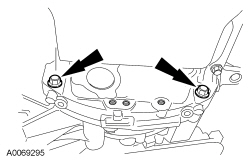
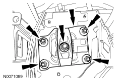
- Remove the 2 engine mount nuts.
- Remove the 2 bolts, stud bolt and the engine mount.
- Remove the 5 transaxle mount nuts and the transaxle mount plate.
- Lower the engine and transaxle assembly from the vehicle.
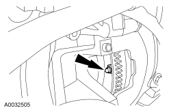
- Remove the nut for the HO2S and CMS wire connector bracket.
- Remove the nut and position the HO2S and CMS wire connector bracket aside.
- Disconnect the Output Shaft Speed (OSS) sensor electrical connector.
- Disconnect the Turbine Shaft Speed (TSS) sensor electrical connector.
- Disconnect the A/C compressor electrical connector.
- Disconnect the Power Steering Pressure (PSP) switch electrical connector.
- Detach the 2 Crankshaft Position (CKP) sensor wire harness retainers.
- Disconnect the CKP sensor electrical connector.
- Remove the 2 nuts and disconnect the starter motor electrical terminals.
- Detach the starter wire harness retainer from the starter motor stud bolt.
- Remove the nut from the starter motor stud bolt and remove the power steering tube bracket.
- Remove the bolt and the engine ground wire.
- Remove the 2 power steering tubes and the wiring harness as an assembly.
- Remove the bolt, stud bolt and the starter.
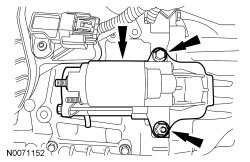
- Remove the starter isolator.
- NOTE:
Mark one stud and the flexplate for assembly reference.
Remove the 4 torque converter nuts.
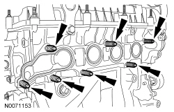
- Remove and discard the 7 catalytic converter manifold studs.
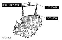
- NOTE:
Lower the engine to within a few inches of the floor.
Using the Floor Crane, Engine Lifting Bracket and Spreader Bar, remove the engine and transaxle assembly from the lift table.
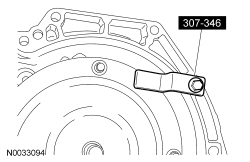
- Remove the 2 bellhousing-to-engine bolts, 2 stud bolts and separate the engine and transmission.
- Install the Torque Converter Retainer, to prevent damage to the torque converter.
 Engine - Automatic Transaxle - Engine - 2.0L - Installation
Special Tool(s)
2,200# Floor Crane, Fold Away
300-OTC1819E or equivalent
Lifting Bracket, Engine
303-050 (T70P-6000)
Powertrain ...
 Engine - Manual Transaxle - Engine - 2.0L - Installation
Special Tool(s)
2,200# Floor Crane, Fold Away
300-OTC1819E or equivalent
Lifting Bracket, Engine
303-050 (T70P-6000)
Powertrain ...
More about Ford Focus:
Ford Focus Compressor to Condenser Discharge Line
Material
Item
Specification
Motorcraft® PAG Refrigerant Compressor Oil
YN-12-D
WSH-M1C231-B
Item
Part Number
Description
1
W520413
A/C compressor discharge fitting nut
2
W520101
Compressor-to-condenser ...
