Ford Focus Service Manual: Engine - Automatic Transaxle - Engine - 2.0L - Installation

|
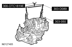
2,200# Floor Crane, Fold Away 300-OTC1819E or equivalent |

|
Lifting Bracket, Engine 303-050 (T70P-6000) |

|
Powertrain Lift 300-OTC1585AE or equivalent |

|
Spreader Bar 303-D089 (D93P-6001-A3) or equivalent |

|
Adjustable Grip Arm, 1735A 014-00001 or equivalent |
| Item | Specification |
|---|---|
| Motorcraft® SAE 5W-20 Premium Synthetic Blend Motor Oil (US); Motorcraft® SAE 5W-20 Super Premium Motor Oil (Canada) XO-5W20-QSP (US); CXO-5W20-LSP12 (Canada) | WSS-M2C945-A |
| Motorcraft® Multi-Purpose Grease XL-5 | ESB-M1C93-B |
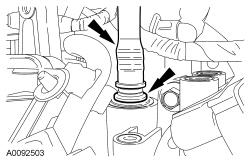
- NOTE:
Lubricate the torque converter pilot hub with multi-purpose grease.
Check the installation depth of the torque converter.
- Lay a straightedge on the automatic transaxle flange.
- Check the installation depth between the transaxle flange and the torque converter centering spigot for the correct clearance.

- Using the Floor Crane and Spreader Bar, position the engine and transaxle
together. Install the 6 bellhousing-to-engine fasteners.
- Tighten to 48 Nm (35 lb-ft).
- Using the Floor Crane, Engine Lifting Bracket and Spreader Bar, raise the engine and transaxle assembly onto the lift table.
- Using the Powertrain Lift and Adjustable Grip Arm, secure the engine and transaxle assembly to the lift table.

- Install the 7 new catalytic converter manifold studs.
- Tighten to 17 Nm (150 lb-in).
- NOTICE: Only rotate the engine in a clockwise direction or engine damage
may occur.
NOTE:
If new parts are not being used, be sure to align the marks on the flexplate and the stud made during engine removal.
Install the 4 torque converter nuts.- Tighten to 35 Nm (26 lb-ft).
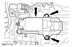
- Install the starter motor isolator.
- Install the starter motor, stud bolt and the bolt.
- Install the upper bolt and lower stud bolt finger-tight.
- Tighten the upper bolt to 35 Nm (26 lb-ft).
- Tighten the lower stud bolt to 35 Nm (26 lb-ft).
- Position the 2 power steering tubes and the wiring harness as an assembly on the engine.
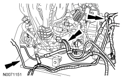
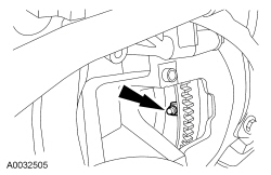
- Install the engine ground wire and the bolt.
- Tighten to 48 Nm (35 lb-ft).
- Install the power steering tube bracket on the starter motor stud bolt and
install the nut.
- Tighten to 20 Nm (177 lb-in).
- Attach the starter wire harness retainer to the starter motor stud bolt.
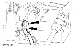
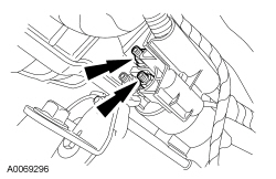
- Connect the starter motor electrical terminals and install the 2 nuts.
- Tighten the small nut to 5 Nm (44 lb-in).
- Tighten the large nut to 12 Nm (106 lb-in).
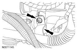
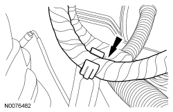
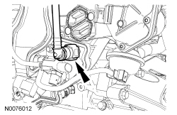
- Connect the Crankshaft Position (CKP) sensor electrical connector.
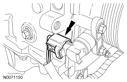
- Attach the 2 CKP sensor wire harness retainers.
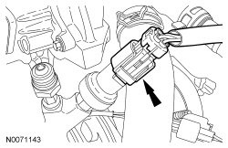
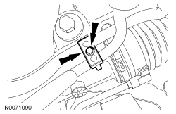
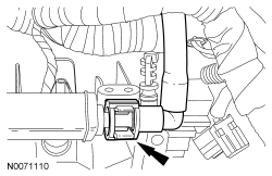
- Connect the Power Steering Pressure (PSP) switch electrical connector.
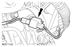
- Connect the A/C compressor electrical connector.
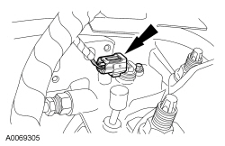
- Connect the Turbine Shaft Speed (TSS) sensor electrical connector.
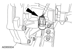
- Connect the Output Shaft Speed (OSS) sensor electrical connector.
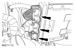
- Position the Heated Oxygen Sensor (HO2S) and Catalyst Monitor Sensor (CMS)
wire connector bracket and install the nut.
- Tighten to 25 Nm (18 lb-ft).
- Install the nut for the HO2S and CMS wire connector bracket.
- Tighten to 25 Nm (18 lb-ft).
- Using the lift table, position the engine and transaxle assembly in the vehicle.
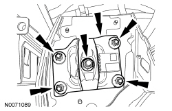
- Install the transaxle mount plate and the 5 nuts.
- Tighten the center nut to 150 Nm (111 lb-ft).
- Tighten the 4 outer nuts to 48 Nm (35 lb-ft).
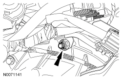
- Install the engine mount and the 2 bolts and the stud bolt.
- Tighten to 48 Nm (35 lb-ft).
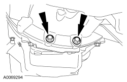
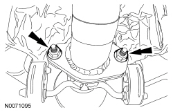
- Install the 2 motor mount nuts.
- Tighten to 90 Nm (66 lb-ft).
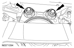
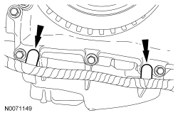
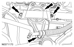
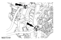
- Install the 2 oil pan-to-bellhousing bolts.
- Tighten to 48 Nm (35 lb-ft).
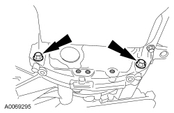
- Install the 2 lower bellhousing-to-oil pan bolts.
- Tighten to 48 Nm (35 lb-ft).
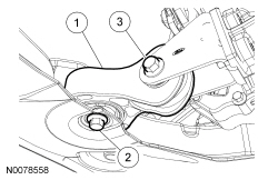
- NOTE:
The bolts are different lengths, make sure the bolts are in the correct location.
Install the transaxle roll restrictor and the 2 bolts.
- Install the transaxle roll restrictor.
- Install the short bolt.
- Install the long bolt.
- Tighten to 70 Nm (52 lb-ft).
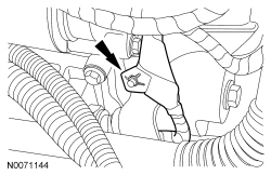
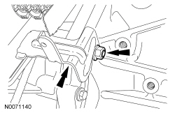
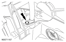
- Position the transaxle fluid indicator tube and install the bolt.
- Tighten to 8 Nm (71 lb-in).
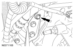
- Install the transaxle fluid indicator tube bracket bolt.
- Tighten to 8 Nm (71 lb-in).
- Attach the wire harness retainer to the transaxle fluid indicator tube.

- Install the transaxle fluid indicator.
- Connect the throttle control electrical connector.
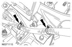
- Connect the heater hose to the coolant tube.
- Connect the upper radiator hose, the heater hose to the coolant bypass.
- Install the power steering pump. For additional information, refer to Section 211-02.
- Clean and inspect the catalytic converter flange. Refer to Exhaust Manifold Cleaning and Inspection in Section 303-00.
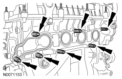
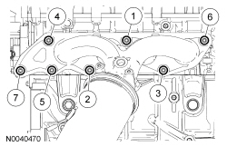
- NOTICE: Failure to tighten the catalytic converter nuts to specification
before installing the converter bracket bolts will cause the converter to develop
an exhaust leak.
NOTICE: Failure to tighten the catalytic converter nuts to specification a second time will cause the converter to develop an exhaust leak.
Using a new gasket and 7 new nuts, install the catalytic converter and tighten in 2 stages in the sequence shown.- Stage 1: Tighten to 55 Nm (41 lb-ft).
- Stage 2: Tighten to 55 Nm (41 lb-ft).
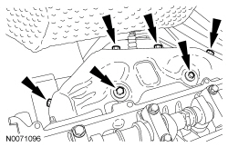
- Install the heat shield and 6 bolts.
- Tighten to 11 Nm (97 lb-in).
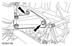
- Install the catalytic converter support bracket and the 2 bolts.
- Tighten to 22 Nm (16 lb-ft).
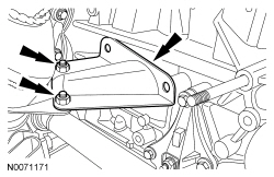
- Install the 2 catalytic converter support bracket-to-engine bolts.
- Tighten to 48 Nm (35 lb-ft).
- NOTE:
Clean the mating surfaces of the muffler and tail pipe assembly and flexpipe.
Using a new gasket and 2 new nuts, connect the flexpipe to the muffler and tail pipe assembly.
- Tighten to 48 Nm (35 lb-ft).
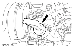
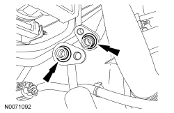
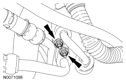
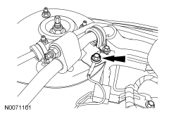
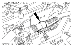
- Using 2 new O-ring seals, install the power steering tubes to the steering
gear and install the bolt.
- Tighten to 18 Nm (159 lb-in).
- Install the power steering tube clip and the bolt.
- Install the LH halfshaft. For additional information, refer to Section 205-04.
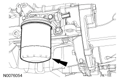
- NOTE:
Lubricate the engine oil filter gasket with clean engine oil prior to installing the oil filter.
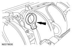
Install a new engine oil filter.
- Tighten the oil filter three-fourths turn after the oil filter gasket makes contact with the oil filter adapter.
- Connect the lower radiator hose to the radiator.
- Install the cooling fan motor and shroud. For additional information, refer to Section 303-03.
- Using 2 new O-ring seals, connect the A/C tubes to the compressor.
- Install the A/C tube bracket to the A/C compressor stud bolt and install
the nut.
- Tighten to 10 Nm (89 lb-in).
- Install the 2 A/C tube nuts.
- Tighten to 15 Nm (133 lb-in).
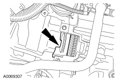
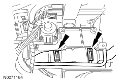
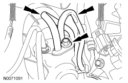
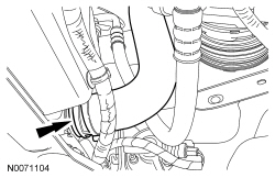
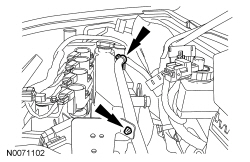
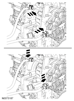
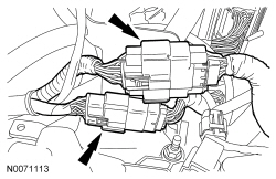
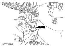
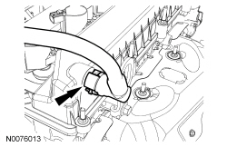
- Position and attach the 4 B+ battery cable wire harness retainers (2 shown).
- Install the generator. For additional information, refer to Section 414-00.
- Install the accessory drive belt and tensioner. For additional information, refer to Section 303-05.
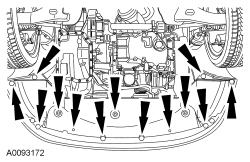
- Install the splash shield and the retainers.
- Install the 2 front wheels and tires. For additional information, refer to Section 204-04.
- Install the radio capacitor ground cable and the bolt.
- Tighten to 10 Nm (89 lb-in).
- Install the engine oil level indicator.
- Attach the shift cable to the retainer.

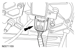
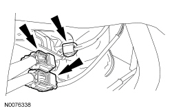
- Connect the 2 transaxle electrical connectors.
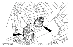
- Install the transmission fluid cooler tubes on the transaxle and slide the latches to the locked position.
- Install the secondary latches.
- Connect the transaxle shift cable to the lever and bracket.
- Connect the HO2S and CMS electrical connectors and attach the wire harness retainer.
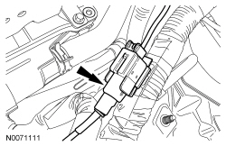
- Connect the starter wire harness electrical connector.
- Connect the 3 PCM electrical connectors.
- Attach the engine harness to the coolant outlet bracket harness retainer.
- Connect and attach the 2 engine harness electrical connectors.
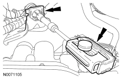
- Attach the brake booster vacuum hose retainer.
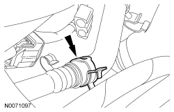
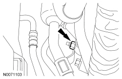
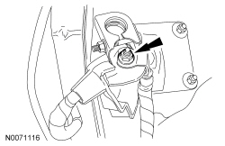
- Install the power brake booster vacuum tube into the quick connect fitting.
- Position and connect the Evaporative Emission (EVAP) tube. For additional information, refer to Section 310-00.
- Connect the fuel tube quick connect coupling to the fuel rail. For additional information, refer to Section 310-00.
- Install the negative battery cable ground and the bolt.
- Tighten to 6 Nm (53 lb-in).
- Attach the 2 positive battery cable wire harness retainer.
- Connect the positive battery cable nut.
- Tighten to 10 Nm (89 lb-in).
- Install the battery tray. For additional information, refer to Section 414-01.
- Connect the crankcase vent tube to the valve cover.
- Install the Air Cleaner (ACL) and ACL outlet pipe. For additional information, refer to Section 303-12.
- Fill the engine with clean engine oil.
- Fill and bleed the cooling system. For additional information, refer to Section 303-03.
- Evacuate and charge the A/C system. For additional information, refer to Section 412-00.
 Engine - 2.0L - Disassembly
Special Tool(s)
Alignment Plate, Camshaft
303-465 (T94P-6256-CH)
Holding Tool, Crankshaft Damper
303-1416
Holding Tool, Flywhe ...
 Engine - Automatic Transaxle - Engine - 2.0L
Special Tool(s)
2,200# Floor Crane, Fold Away
300-OTC1819E or equivalent
Lifting Bracket, Engine
303-050 (T70P-6000)
Powertrain ...
More about Ford Focus:
Ford Focus Coolant Pump
Material
Item
Specification
Motorcraft® Premium Gold Engine Coolant
VC-7-B (US); CVC-7-B (Canada)
WSS-M97B51-A1
Coolant Expansion Tank
Item
Part Number
Description
1
W701107
Coolant expansion tank bolt (2 required)
...
