Ford Focus Service Manual: Output Shaft - Disassembly and Assembly of Subassemblies

|
Adapter Set, Step Plate 205-DS011 (D80L-630-A) |

|
Remover, Bearing/Gear 205-D064 (D84L-1123-A) |

|
Remover/Installer, Bearing Tube 308-052 (T77J-7025-B) |
| Item | Specification |
|---|---|
| Motorcraft® Full Synthetic Manual Transmission Fluid XT-M5-QS | WSD-M2C200-C |
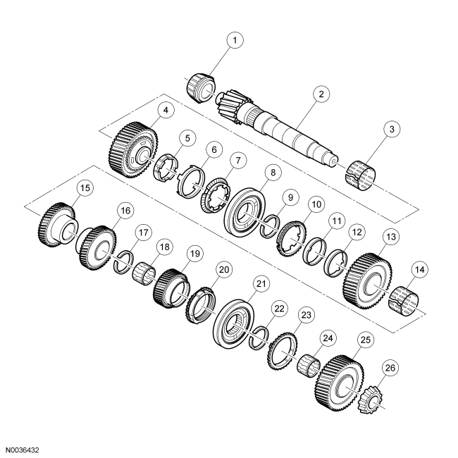
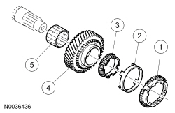
Output Shaft
| Item | Part Number | Description |
|---|---|---|
| 1 | — | Output shaft bearing |
| 2 | — | Output shaft |
| 3 | — | First gear needle bearing |
| 4 | — | First gear |
| 5 | — | First gear inner synchronizer ring |
| 6 | — | First gear synchronizer cone |
| 7 | — | First gear outer synchronizer ring |
| 8 | — | First/second gear synchronizer assembly |
| 9 | — | Snap ring |
| 10 | — | Second gear synchronizer ring |
| 11 | — | Second gear synchronizer cone |
| 12 | — | Second gear inner synchronizer ring |
| 13 | — | Second gear |
| 14 | — | Second gear needle bearing |
| 15 | — | Third gear |
| 16 | — | Fourth gear |
| 17 | — | Snap ring |
| 18 | — | Fifth gear needle bearing |
| 19 | — | Fifth gear |
| 20 | — | Fifth gear synchronizer ring |
| 21 | — | Fifth/reverse gear synchronizer assembly |
| 22 | — | Snap ring |
| 23 | — | Reverse gear synchronizer ring |
| 24 | — | Reverse gear needle bearing |
| 25 | — | Reverse gear |
| 26 | — | Output shaft bearing |
Disassembly
NOTE:
The inner synchronizer ring and the synchronizer cone must be handled very carefully.
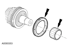
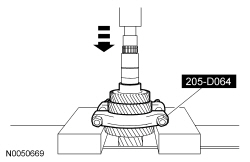
- NOTICE: Only loosely attach the Bearing/Gear Remover to avoid damaging
the synchronizer ring.
Using a press and the Bearing/Gear Remover, remove the output shaft bearing and the reverse gear. Discard the output shaft bearing.

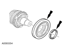
- Remove the reverse gear needle bearing and the synchronizer ring.
- Remove and discard the snap ring and the 5th/reverse gear synchronizer assembly.
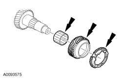
- Remove the synchronizer ring, 5th gear and 5th gear needle bearing.
- Check all components for wear or damage. Install new components as necessary.
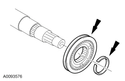
- NOTE:
Position the Bearing/Gear Remover with the flat side upward.
Using the Bearing/Gear Remover, remove and discard the snap ring, then remove the 4th gear.
- Check 4th gear for wear or damage. Install a new gear as necessary.

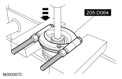
- NOTE:
Position the Bearing/Gear Remover with the flat side upward.
Using the Bearing/Gear Remover, remove the 2nd and the 3rd gear.
- Check 2nd and 3rd gear for wear or damage. Install new gears as necessary.
- Remove the following:
- Outer synchronizer ring
- Synchronizer cone
- Inner synchronizer ring
- Second gear
- Second gear needle bearing
- Check all components for wear or damage. Install new components as necessary
- Remove and discard the snap ring, then remove the 1st/2nd gear synchronizer
hub assembly.
- Check the synchronizer for wear or damage. Install a new synchronizer as necessary.
- Remove the following:
- Outer synchronizer ring
- Inner synchronizer ring
- Synchronizer cone
- First gear
- First gear needle bearing
- Check all components for wear or damage. Install new components as necessary
- Using the Bearing/Gear Remover, remove the clutch housing roller bearing.
- NOTE:
Mark the installed position of the selector ring.
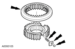
Disassemble the 1st/2nd and 5th/reverse synchronizer hub assemblies. Take care when pulling the selector ring from the synchronizer hub. The detent balls are spring-loaded. Remove the selector ring from the synchronizer hub. Remove the compression springs, the keys and the detent balls.
- Inspect the synchronizer assemblies.
- Check for worn, nicked or broken teeth. Install a new synchronizer as necessary.
- Check keys for wear or distortion. Install a new synchronizer as necessary.
- Check springs for distortion. Install a new synchronizer as necessary.
Assembly
- NOTE:
Do not lubricate new roller bearings.
Lubricate all other transmission components with transmission fluid during reassembly.
- NOTE:
Handle the inner synchronizer ring and synchronizer cone very carefully.
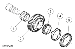
Install the following:
- First gear needle bearing
- First gear
- Inner synchronizer ring
- Synchronizer cone
- Outer synchronizer ring
- NOTE:
Observe the markings on the selector ring.
NOTE:
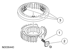
Place a rubber band around the synchronizer body. Install the springs, the synchronizer bars and detent balls. Slide the synchronizer sleeve over the synchronizer body, while moving the rubber band downward.
Assemble the synchronizer hub assembly.- Install the compression springs.
- Install the keys and the detent balls in the gear synchronizer hub against the force of the spring.
- Align the selector ring with the hub and push it on.
- NOTE:
Install the synchronizer hub assembly with the larger collar facing toward 2nd gear.
Install the 1st/2nd gear synchronizer hub assembly, then install a new snap ring.
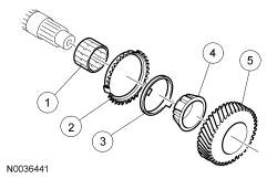
- Install the following:
- Second gear needle bearing
- Outer synchronizer ring
- Synchronizer cone
- Inner synchronizer ring
- Second gear
- Using a press and the Bearing Tube Remover/Installer, install 3rd gear.
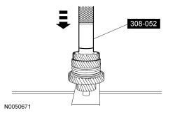
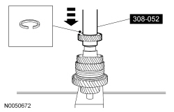
- Using a press and the Bearing Tube Remover/Installer, install 4th gear. Install a new snap ring.
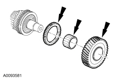
- Install the 5th gear needle bearing, 5th gear and the synchronizer ring.
- NOTE:
Install the synchronizer hub assembly with the small collar and the ring groove facing outward.
Install the 5th/reverse gear synchronizer assembly and a new snap ring.
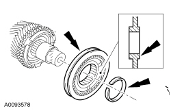
- Install the synchronizer ring, the reverse gear needle bearing and the reverse gear.
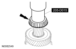
- Using a Step Plate Adapter Set and a press, press the bearing on by the inner race only. Install a new output shaft bearing.
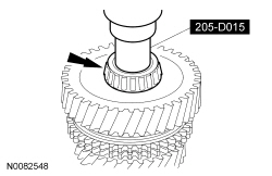
- Using a Step Plate Adapter Set and a press, press the bearing on by the inner race only. Install a new output shaft bearing.

 Output Shaft Speed (OSS) Sensor
Material
Item
Specification
Motorcraft® MERCON® LV Automatic Transmission Fluid
XT-10-QLVC (US); CXT-10-LV12 (Canada)
MERCON® LV
Output Shaft Speed (OSS) Sen ...
More about Ford Focus:
Ford Focus Ride Height Measurement
Front Ride Height Measurement
Item
Description
1
Ride height = 2 - 3
2
Measurement 2
3
Measurement 3
NOTE: Make sure that the vehicle is positioned on a flat, level surface
and the tires are inflated to the ...
