Ford Focus Service Manual: Rear Suspension Wheel Knuckle
| Item | Part Number | Description |
|---|---|---|
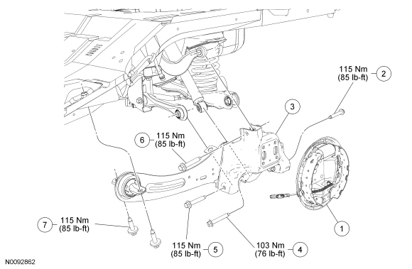
| 1 | 2210 | Drum brake assembly |
| 2 | W500746 | Rearward lower arm outboard bolt |
| 3 | 5A969 LH/ 5A968 RH | Wheel knuckle and trailing arm assembly |
| 4 | W709634 | Shock absorber lower bolt |
| 5 | W500744 | Forward lower arm outboard bolt |
| 6 | W500744 | Upper arm outboard bolt |
| 7 | W709647 | Trailing arm bolt (2 required) |
| Item | Part Number | Description |
|---|---|---|
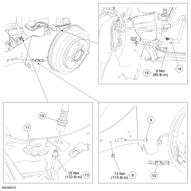
| 8 | W703313 | Parking brake cable bolt |
| 9 | 2A635 | Parking brake cable |
| 10 | — | Parking brake cable connector (part of 2A635) |
| 11 | W700936 | Brake tube fitting clip |
| 12 | 2282 | Brake hose |
| 13 | — | Brake tube fitting (part of 2268B) |
| 14 | — | Wheel speed sensor harness clip (part of 2C204) |
| 15 | W500012 | Wheel speed sensor bolt |
| Item | Part Number | Description |
|---|---|---|
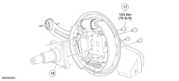
| 16 | 4A492 | Wheel spindle |
| 17 | W704332 | Wheel spindle bolt (4 required) |
Removal
NOTICE: Suspension fasteners are critical parts because they affect performance of vital components and systems and their failure may result in major service expense. New parts must be installed with the same part numbers or equivalent part, if replacement is necessary. Do not use a replacement part of lesser quality or substitute design. Torque values must be used as specified during reassembly to make sure correct retention of these parts.
All vehicles
- Remove the brake drum. For additional information, refer to Section 206-02.
Vehicles equipped with ABS
- Remove the wheel speed sensor bolt and disconnect the sensor.
- Disconnect the wheel speed sensor harness clip from the trailing arm and position the harness and sensor aside.
All vehicles
- Disconnect the brake tube fitting and remove the clip.
- Disconnect the parking brake cable.
- Remove the 4 wheel spindle bolts, spindle and the rear brake assembly.
- Discard the bolts.
- Remove the bolt and disconnect the parking brake cable from the trailing arm.
- Remove and discard the 2 trailing arm bolts.
- Remove and discard the shock absorber lower bolt.
- Remove and discard the forward lower arm outboard bolt.
- Remove and discard the rearward lower arm outboard bolt.
- Remove and discard the upper arm outboard bolt and remove the wheel knuckle and trailing arm assembly.
Installation
All vehicles
- NOTE:
Do not tighten the bolt at this time.
Position the wheel knuckle and trailing arm assembly and loosely install the new upper arm outboard bolt.
- NOTE:
Do not tighten the bolt at this time.
Loosely install the new rearward lower arm outboard bolt.
- NOTE:
Do not tighten the bolt at this time.
Loosely install the new forward lower arm outboard bolt.
- NOTE:
Do not tighten the bolt at this time.
Loosely install the new shock absorber lower bolt.
- NOTE:
Do not tighten the bolt at this time.
Loosely install the 2 new trailing arm bolts.
- Connect the parking brake cable to the trailing arm and install the bolt.
- Tighten to 13 Nm (115 lb-in).
- Connect the brake tube fitting and install the clip.
- Tighten to 15 Nm (133 lb-in).
Vehicles equipped with ABS
- Position the wheel speed sensor and install the bolt.
- Tighten to 9 Nm (80 lb-in).
- Position the wheel speed sensor harness and connect the harness to the trailing arm clip.
All vehicles
- Position the rear brake assembly and install the new wheel spindle and 4
bolts.
- Tighten to 103 Nm (76 lb-ft).
- Install the brake drum. For additional information, refer to Section 206-02.
- Lower the vehicle until the weight of the vehicle is resting on the wheels and tires.
- Tighten the 2 trailing arm bolts to 115 Nm (85 lb-ft).
- Tighten the shock absorber lower bolt to 103 Nm (76 lb-ft).
- Tighten the forward lower arm outboard bolt to 115 Nm (85 lb-ft).
- Tighten the rearward lower arm outboard bolt to 115 Nm (85 lb-ft).
- Tighten the upper arm outboard bolt to 115 Nm (85 lb-ft).
- Bleed the brake wheel cylinder. For additional information, refer to Section 206-00 for component bleeding.
- Check and, if necessary, adjust the rear toe. For additional information, refer to Section 204-00.
 Front Suspension Wheel Knuckle
Special Tool(s)
Installer, Halfshaft
204-161 (T97P-1175-A)
Remover, Front Wheel Hub
205-D070 (D93P-1175-B) or equivalent
Remove ...
 Strut Assembly
...
More about Ford Focus:
Ford Focus Strut and Spring Assembly - Disassembly and Assembly
Item
Part Number
Description
1
5310
Spring
2
18198
Spring upper seat and bearing assembly
3
3K155
Upper mount bearing
4
W711949
Strut rod nut
5
18A047
Dust boot
6
3025
Jounce ...
