Ford Focus Service Manual: Steering Gear

|
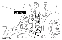
Remover, Tie-Rod End 211-001 (Tool-3290-D) |
| Item | Specification |
|---|---|
| MERCON® V Automatic Transmission Fluid XT-5-QM (or XT-5-QMC) (US); CXT-5-LM12 (Canada) | MERCON® V |
NOTE:
Vehicles with 15- and 16-in wheels shown.
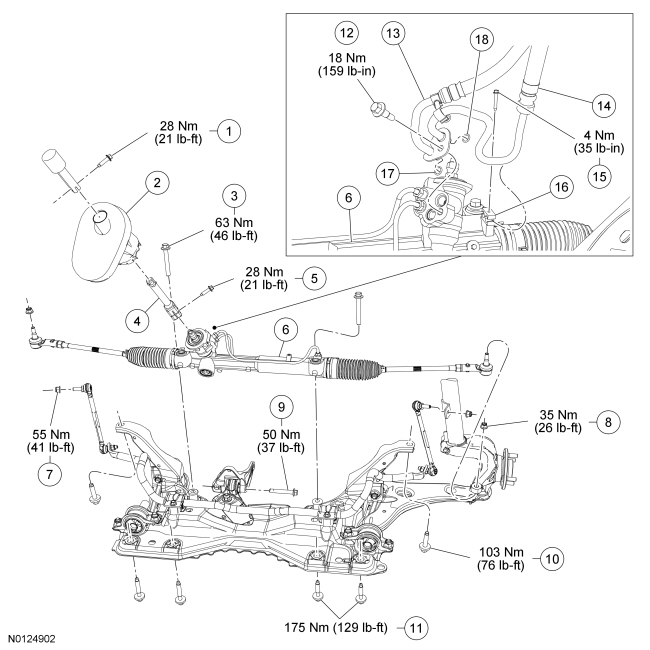
| Item | Part Number | Description |
|---|---|---|
| 1 | W706229 | Upper steering column shaft-to-lower steering column shaft bolt |
| 2 | 3D677 | Dash seal |
| 3 | W706981 | Steering gear bolt (2 required) |
| 4 | 3N997 | Lower steering column shaft |
| 5 | W702825 | Lower steering column shaft-to-steering gear bolt |
| 6 | 3504 | Steering gear |
| 7 | W520103 | Stabilizer bar link upper nut (2 required) |
| 8 | W520203 | Outer tie-rod end nut |
| 9 | W702801 | Transaxle roll restrictor bolt |
| 10 | W500562 | Upper subframe bolt (2 required) |
| 11 | W703719 | Lower subframe bolts (4 required) |
| 12 | W704331 | Steering line clamp plate bolt |
| 13 | 3A713 | Return line |
| 14 | 3A719 | Pressure line |
| 15 | W702164 | Steering line-to-steering gear bolt |
| 16 | W704373 | Steering line-to-steering gear retainer |
| 17 | 3F886-BA | O-ring seal |
| 18 | 3F886-AA | O-ring seal |
Removal
NOTICE: Steering fasteners are critical parts because they affect performance of vital components and systems and their failure may result in major service expense. New parts must be installed with the same part numbers or equivalent part, if replacement is necessary. Do not use a replacement part of lesser quality or substitute design. Torque values must be used as specified during reassembly for correct retention of these parts.
NOTICE: While repairing the power steering system, care should be taken to prevent the entry of foreign material or failure of the power steering components may result.
- Using a suitable holding device, hold the steering wheel in the straight-ahead position.

- NOTICE: Do not allow the steering column to rotate while the steering
column shaft is disconnected or damage to the clockspring may result. If there
is evidence that the steering column has rotated, the clockspring must be removed
and recentered. For additional information, refer to Section 501-20B.
Remove the upper steering column shaft-to-lower steering column shaft bolt.
- Discard the bolt.
- Remove the wheels and tires. For additional information, refer to Section 204-04.
- NOTICE: Leave the outer tie-rod end nuts in place to protect the ball
studs from damage.
NOTE:
Use the hex-holding feature to prevent turning of the stud while loosening the nut.
Loosen the 2 outer tie-rod end nuts.
- NOTICE: Protect the ball joint seal to prevent damage.
Using the Tie-Rod End Remover, separate the outer tie-rod ends from the wheel knuckles.
- Remove and discard the outer tie-rod end nuts.
- NOTE:
Use the hex-holding feature to prevent turning of the stud while removing the nut.
Remove the 2 stabilizer bar link upper nuts and disconnect the stabilizer bar links from the struts.
- Discard the nuts.
- Remove the engine support insulator-to-transaxle bracket bolt.
- Remove the steering line-to-steering gear retainer bolt and the retainer.
- Remove the bolt, rotate the steering line clamp plate and disconnect the
pressure and return lines from the steering gear.
- Discard the O-ring seals.
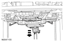
- Using a suitable jack, support the subframe.
- Remove the 2 upper and 4 lower subframe bolts.
- NOTE:
It is not necessary to separate the lower ball joints from the wheel knuckle when lowering the subframe.
Lower the subframe.
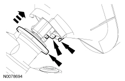
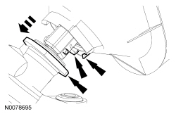
- Pull out on the dash seal tabs and push the dash seal upward to detach it
from the steering gear.
- Position the dash seal aside.
- Remove the bolt and disconnect the lower steering column shaft from the
steering gear.
- Discard the bolt.
- Remove the 2 steering gear bolts and the steering gear.
- Discard the bolts.
Installation
- NOTICE: New O-ring seals must be installed any time the pressure and
return lines are disconnected from the steering gear or a fluid leak may occur.
Install new O-ring seals on the pressure and return lines.
- Position the steering gear and install 2 new steering gear bolts.
- Tighten to 63 Nm (46 lb-ft).
 WARNING: Install
a new steering column shaft bolt. Reuse could result in bolt failure and loss of vehicle control. Failure to follow this instruction may result in serious injury to vehicle occupant(s).Connect the lower steering column shaft to the steering gear and install the new bolt.
- Tighten to 28 Nm (21 lb-ft).
- Install the dash seal to the steering gear.
- Center the dash seal on the steering gear and pull down to attach it to the steering gear.
- NOTICE: While tightening the subframe bolts, make sure the front subframe
does not move. Misalignment of the subframe during bolt installation may damage
the bolts and/or subframe.
Using a suitable jack, raise the front subframe and loosely install the 2 upper and 4 lower subframe bolts.
- Tighten the 4 lower subframe bolts to 175 Nm (129 lb-ft).
- Tighten the 2 upper subframe bolts to 103 Nm (76 lb-ft).
- Install the pressure and return lines to the power steering gear, rotate
the steering line clamp plate and install the bolt.
- Tighten to 18 Nm (159 lb-in).
- Position the steering line retainer and install the steering line-to-steering
gear bolt.
- Tighten to 4 Nm (35 lb-in).
- Install the transaxle roll restrictor bolt.
- Tighten to 50 Nm (37 lb-ft).
- Connect the stabilizer bar links to the struts and install 2 new nuts.
- Tighten to 55 Nm (41 lb-ft).
- WARNING: Do
not reuse a tie rod-to-wheel knuckle nut. This can result in nut failure and loss of steering control. Failure to follow this instruction may result in serious injury to vehicle occupant(s).Install 2 new outer tie-rod end nuts.
- Tighten to 35 Nm (26 lb-ft).
- Install the wheels and tires. For additional information, refer to Section 204-04.
- WARNING: Install
a new steering column shaft bolt. Reuse could result in bolt failure and loss of vehicle control. Failure to follow this instruction may result in serious injury to vehicle occupant(s).Connect the upper steering column shaft to the lower steering column shaft and install the new bolt.
- Tighten to 28 Nm (21 lb-ft).
- Fill the power steering system. For additional information, refer to Section 211-00.
- Check and, if necessary, adjust the front toe. For additional information, refer to Section 204-00.

 Steering Gear Boot
Special Tool(s)
Boot Clamp Pliers
205-D067 (D87P-1098-A) or equivalent
Material
Item
Specification
Premium Long-Life Grease
XG-1-C or XG-1 ...
More about Ford Focus:
Ford Focus Transaxle - Installation (Automatic Transaxle/Transmission — 4F27E)
Special Tool(s)
Adapter for 303-290A
303-290-01
Adapter for 303-290A (Support Leg)
303-290-03A
Retainer, Torque Converter
307-346 (T97T-7902-A)
Support Bar, Engine
303-290A
Material
...
