Ford Focus Service Manual: Transaxle - Installation (Manual Transaxle/Transmission — MTX75)
| Item | Specification |
|---|---|
| Motorcraft® Full Synthetic Manual Transmission Fluid XT-M5-QS | WSD-M2C200-C |
| High Performance DOT 3 Motor Vehicle Brake Fluid PM-1-C (US); CPM-1-C (Canada) | WSS-M6C62-A or WSS-M6C65-A1 |
| Thread Sealant with PTFE TA-24 | WSK-M2G350-A2 |
Installation
 WARNING: Do not
breathe dust or use compressed air to blow dust from storage containers or friction
components. Remove dust using government-approved techniques. Friction component
dust may be a cancer and lung disease hazard. Exposure to potentially hazardous
components may occur if dusts are created during repair of friction components,
such as brake pads and clutch discs. Exposure may also cause irritation to skin,
eyes and respiratory tract, and may cause allergic reactions and/or may lead to
other chronic health effects. If irritation persists, seek medical attention or
advice. Failure to follow these instructions may result in serious personal injury.
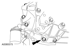
- Position the transaxle to the engine. Install the 10 transaxle-to-engine
bolts.
- Tighten to 47 Nm (35 lb-ft).
- Install the exhaust flexible pipe. For additional information, refer to Section 309-00.
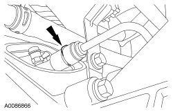
- Connect the clutch hydraulic tube and install the clip.
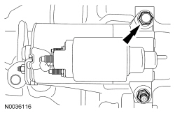
- Tighten the starter bolts.
- Tighten to 25 Nm (18 lb-ft).
- NOTE:
Install a new halfshaft snap ring.
Using a seal protector, install the LH halfshaft into the transaxle.
- NOTE:
Install a new halfshaft snap ring.
Using a seal protector, install the RH halfshaft into the transaxle.
- NOTE:
Install a new intermediate shaft center bearing cap and locknuts.
Install the new intermediate shaft center bearing cap and the locknuts.
- Tighten to 25 Nm (18 lb-ft).
- Connect the Vehicle Speed Sensor (VSS) electrical connector.
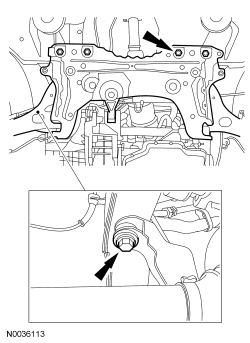
- NOTE:
Make sure to align the index marks on the subframe to the chassis.
Position the subframe into the vehicle, install the 6 subframe bolts.
- Tighten the rear subframe bolts to 200 Nm (148 lb-ft).
- Tighten the front subframe bolts to 115 Nm (85 lb-ft).
- Connect the power steering tubes to the steering gear. Install the power
steering tube bolt.
- Tighten to 23 Nm (17 lb-ft).
- Install the 2 new stabilizer bar link nuts.
- Tighten to 50 Nm (37 lb-ft).
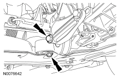
- Position the lower control arms into the wheel knuckles. Install the 2 new
lower control arm bolts and nuts.
- Tighten to 47 Nm (35 lb-ft).
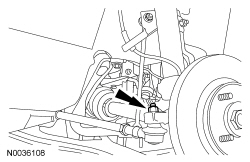
- Install the 2 new tie-rod end nuts.
- Tighten to 47 Nm (35 lb-ft).
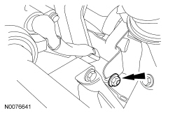
- Install the engine roll restrictor and the 2 engine roll restrictor bolts.
- Tighten to 70 Nm (52 lb-ft).
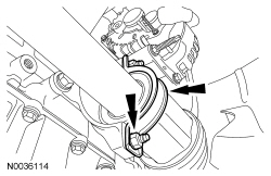
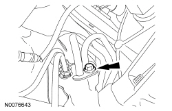
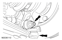
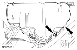
- Position the bracket to the transaxle. Install the lower Heated Oxygen Sensor
(HO2S) sensor bracket nut.
- Tighten to 25 Nm (18 lb-ft).
- Install the wheels and tires. For additional information, refer to Section 204-04.
- Install the 3 upper transaxle-to-engine bolts.
- Tighten to 47 Nm (35 lb-ft).
- Install the upper sensor bracket nut. Connect the HO2S and the catalyst
monitor sensor electrical connectors.
- Tighten to 25 Nm (18 lb-ft).
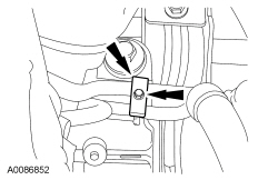
- Connect the clutch hydraulic tube and grommet into the retaining bracket.
- Install the power steering tube clamp bolt.
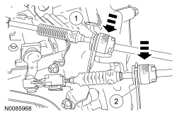
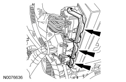
- NOTE:
An audible click will be heard when the gearshift cables are correctly seated in the retaining bracket.
Install the gearshift cables into the brackets.
- Connect the shift cable into the retaining bracket.
- Connect the selector cable into the retaining bracket.
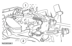
- Connect the gearshift cables to the transaxle.
- Press the release button and connect the shift cable to the shift mass.
- Press the release button and connect the selector cable to the selector lever.
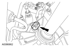
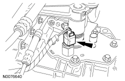
- Connect the reverse lamp switch electrical connector.
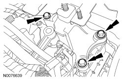
- Install the LH transaxle support insulator bracket and the 3 LH transaxle
support insulator bracket bolts.
- Tighten to 80 Nm (59 lb-ft).
- Install the PCM/battery support bracket.
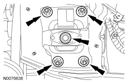
- Install the LH transaxle support insulator and the 5 LH transaxle support
insulator nuts. Install the 3 PCM/battery support bracket bolts.
- Tighten the LH transaxle support insulator center nut to 150 Nm (111 lb-ft).
- Tighten the 4 LH transaxle support insulator outer nuts to 48 Nm (35 lb-ft).
- Install the PCM and the PCM bolt and nut.
- Tighten to 8 Nm (71 lb-in).
- Connect the PCM electrical connectors.
- Install the resonator and the 2 resonator bolts.
- Tighten to 11 Nm (97 lb-in).
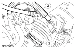
- Install the intake air hose.
- Connect the crankcase ventilation hose.
- Connect the booster bleed hose.
- Tighten the intake air hose clamps.
- Tighten to 4 Nm (35 lb-in).
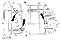
- Install the battery tray and the 3 battery tray nuts. Connect the 2 wiring
harness pushpins.
- Tighten to 12 Nm (106 lb-in).
- Install the battery. For additional information, refer to Section 414-01.
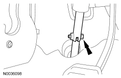
- Install the steering column shaft bolt.
- Tighten to 28 Nm (21 lb-ft).
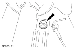
- Check and, if necessary, fill the transaxle with the specified fluid. The total fill capacity is 1.9L (4.0 pt). Apply sealant to the fill plug threads and install the fill plug.
- Fill and bleed the power steering system. For additional information, refer to Section 211-00.
- WARNING: Carefully
read cautionary information on product label. For EMERGENCY MEDICAL INFORMATION seek medical advice. In the USA or Canada on Ford/Motorcraft products call: 1-800-959-3673. For additional information, consult the product Material Safety Data Sheet (MSDS) if available. Failure to follow these instructions may result in serious personal injury.NOTICE: Brake fluid is harmful to painted and plastic surfaces. If brake fluid is spilled on a painted or plastic surface, wash the affected area immediately with cold water.
Fill the brake fluid reservoir to the specified level. Bleed the clutch hydraulic system. For additional information, refer to Section 308-00.
- Adjust the gearshift cables. For additional information, refer to Section 308-00.
 Transaxle - Installation (Automatic Transaxle/Transmission — 4F27E)
Special Tool(s)
Adapter for 303-290A
303-290-01
Adapter for 303-290A (Support Leg)
303-290-03A
Retainer, Torque Converter
3 ...
 Transaxle - Removal (Manual Transaxle/Transmission — MTX75)
Special Tool(s)
Adapter for 303-290A
303-290-01
Adapter for 303-290A (Support Leg)
303-290-03A
Remover, Halfshaft
205-241 (T ...
More about Ford Focus:
Ford Focus Module Controlled Functions
Smart Junction Box (SJB)
The SJB is located under the instrument panel on the driver side (left of the
steering column) has control of the following systems:
Interior lighting
Exterior lighting
Dimmable backlighting
Battery saver function
Delayed accessory relay function
Horn ...
