Ford Focus Service Manual: Engine Cooling - Description and Operation
NOTICE: The engine cooling system is filled with Motorcraft® Premium Gold Engine Coolant. Do not mix coolant types. Mixing coolant types degrades the corrosion protection of Motorcraft® Premium Gold Engine Coolant. Failure to follow these instructions may result in engine or cooling system damage.
NOTICE: Always fill the cooling system with the manufacturer's specified coolant. If a non-specified coolant has been used the cooling system must be chemically flushed. Refer to Cooling System Flushing in this section. Failure to follow these instructions may damage the engine or cooling system.
NOTE:
If cooling system stop leak pellets are used, Motorcraft® Premium Gold Engine Coolant may darken from yellow to golden tan.
The cooling system consists of the:
- radiator.
- cooling fan motor and shroud.
- coolant expansion tank.
- radiator drain valve.
- coolant pump.
- thermostat housing.
- block heater (if equipped).
Engine coolant provides freeze protection, boil protection, cooling efficiency and corrosion protection to the engine and cooling components. In order to obtain these protections, the engine coolant must be maintained at the correct concentration and fluid level in the degas bottle.
When adding engine coolant, use a 50/50 mixture of engine coolant and distilled water. A coolant concentration of 50% will provide freeze point protection down to -37°C (-34°F)
To maintain the integrity of the coolant and the cooling system:
- NOTE:
If cooling system stop leak pellets are used, Motorcraft® Premium Gold Engine Coolant may darken from yellow to golden tan.
Add Motorcraft® Premium Gold Engine Coolant or equivalent (yellow color) meeting Ford specification WSS-M97B51-A1 (yellow color). Do not mix coolant types. Mixing coolants may degrade the coolant's corrosion protection.
- Do not add alcohol, methanol, brine or any engine coolants mixed with alcohol or methanol antifreeze. These can cause engine damage from overheating or freezing.
- Do not mix with recycled coolant unless it meets the requirements of Ford specification WSS-M97B51-A1. Not all coolant recycling processes meet this Ford specification. Use of such a coolant may harm the engine and cooling system components. Do not mix coolant types.
Fail Safe Cooling
The vehicle has a strategy built into the PCM that will control the engine if it starts to overheat.
Stage 1 of the strategy will commence if the engine starts to overheat. The Cylinder Head Temperature (CHT) sensor transmits a signal to the PCM, which then moves the temperature gauge pointer into the red zone.
If the engine is not switched off and the temperature continues to rise, the Powertrain Check Lamp is illuminated. This indicates to the driver that the engine is approaching critical limits and should be stopped. At this point DTC P1285 is set in the PCM which can be retrieved using a scan tool.
Stage 2 of the strategy will commence if the lamp and temperature gauge are ignored by the driver. The PCM will start to control the engine by cutting out 2 cylinders and restricting the rpm to below 3,000 rpm. Simultaneously the Malfunction Indicator Lamp (MIL) will be illuminated. This indicates that long term engine damage can occur and vehicle emissions will be affected. At this point DTC P1299 is set in the PCM which can be retrieved using a scan tool.
Air is then drawn into the deactivated cylinders. This helps to control the temperature of the engine internal components. The deactivated cylinders are alternated to allow even cooling of all the cylinders.
NOTE:
If the driver is using a high percentage of throttle travel (for example, an overtaking maneuver) when the PCM starts engine deactivation (Stage 2), the deactivation will be delayed for 10 seconds.
NOTE:
After 2-cylinder operation has begun, the engine will not revert to 4-cylinder operation, even if the temperature should fall, until the ignition is switched off and then on again.
NOTE:
The MIL can only be extinguished by using a scan tool after the fault has been rectified and the DTC cleared.
Stage 3 of the strategy will commence if the engine temperature still continues to rise. This will result in the engine being totally disabled before major engine damage or seizure occurs. The Powertrain Check Lamp will begin to flash, indicating to the driver that the engine will be switched off after 30 seconds. This allows the driver time to choose a suitable parking place.
Coolant Flow Diagram
NOTE:
Black arrows indicate hot, white arrows indicate cold.
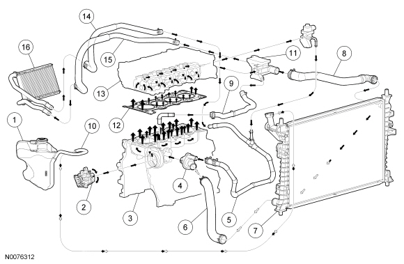
| Item | Part Number | Description |
|---|---|---|
| 1 | 8C045 | Coolant expansion tank |
| 2 | 8501 | Coolant pump |
| 3 | 6010 | Engine block |
| 4 | 8575 | Thermostat housing |
| 5 | 18C266 | Heater hose assembly |
| 6 | 8B273 | Lower radiator hose |
| 7 | 8005 | Radiator |
| 8 | 8B274 | Upper radiator hose |
| 9 | 8A582 | Bypass hose |
| 10 | 8N029 | Coolant expansion tank overflow hose |
| 11 | 8K556 | Coolant outlet adapter |
| 12 | 6051 | Cylinder head gasket |
| 13 | 6090 | Cylinder head |
| 14 | 18K580 | Heater core outlet hose |
| 15 | 18K579 | Heater core inlet hose |
| 16 | 18478 | Heater core |
 Cooling System Flushing
Special Tool(s)
Drain Kit
164-R3662
Flush Kit
164-R3658 or equivalent
Pro Flush and Fill
023-00154 or equivalent
...
 Coolant Pump
Material
Item
Specification
Motorcraft® Premium Gold Engine Coolant
VC-7-B (US); CVC-7-B (Canada)
WSS-M97B51-A1
Coolant Expansion Tank
Ite ...
More about Ford Focus:
Ford Focus General information
CAUTION:
Using the system with the engine off
will drain the battery.
This section describes the functions and
features of the Bluetooth mobile phone
hands free system.
The Bluetooth mobile phone part of the
system provides interaction with the audio
or navigation system and your mobile
...
Nissan Frontier - Instrument Panel - Keys - Brake system
