Ford Focus Service Manual: Fluorescent Dye Leak Detection

|
Cordless/Rechargeable True UV LED Light ES 023-00182 or equivalent |

|
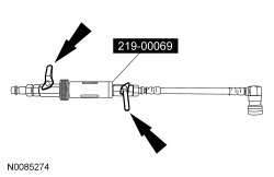
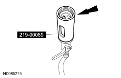
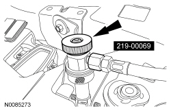
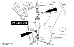
R-134a Loop/Add On Injector Kit-Set 219-00069 or equivalent |

|
R-134a Manifold Gauge Set 300-R0B40134AE or equivalent |

|
R-134a Refrigerant Management Machine (SAE J-2788 Compliant) 300-R0B34788-PROE or equivalent |

|
R-134a Refrigerant Management Machine (SAE J-2788 Compliant) 199-00067 or equivalent |

|
R-134a Refrigerant Management Machine (SAE J-2788 Compliant) 265-00012 or equivalent |
| Item | Specification |
|---|---|
| Stay-Brite® R-134a Leak Detection Dye 164-R6060 (Rotunda) | — |
Fluorescent Dye Injection Using a R-134a Refrigerant Management Machine and Dye Injector — Vehicles Requiring R-134a Addition
NOTE:
This method of fluorescent dye injection requires the addition of R-134a from a R-134a Refrigerant Management Machine or R-134a Manifold Gauge Set hooked to an external tank to charge the dye into the refrigerant system. If adding fluorescent dye to a refrigerant system that is already fully charged, the R-134a Loop/Add On Injector Kit-Set method should be used.
NOTE:
Fluorescent refrigerant system dye is added to the refrigerant system at the factory to assist in refrigerant system leak diagnosis using a Rotunda-approved UV blacklight. It is not necessary to add additional dye to the refrigerant system before diagnosing leaks, even if a significant amount of refrigerant has been removed from the system. Replacement suction accumulators and receiver/driers are shipped with a fluorescent dye "wafer" included in the desiccant bag which will dissolve after approximately 30 minutes of continued A/C operation. It is not necessary to add dye after flushing or filtering the refrigerant system because a new suction accumulator or receiver/drier is installed as part of the flushing or filtering procedure. Additional refrigerant system dye should only be added if more than 50% of the refrigerant system lubricant capacity has been lost due to a fitting separation, hose rupture or other damage.
NOTE:
Before using the R-134a Loop/Add On Injector Kit-Set for the first time, refer to the manufacturer's instructions on evacuation of any non-condensable gases from the hoses.
NOTE:
Only connect the dye/lubricant injector from the R-134a Loop/Add On Injector Kit-Set when fluorescent dye is to be injected. The dye/lubricant injector has a one-way check valve that will prevent refrigerant system recovery and evacuation.
- NOTE:
If no R-134a pressure is present in the refrigerant system, the system should be evacuated before carrying out the injection procedure. For additional information, refer to Air Conditioning (A/C) System Recovery, Evacuation and Charging in this section.
Connect a R-134a Refrigerant Management Machine or a R-134a Manifold Gauge Set to the refrigerant system service port valves.
- Verify that the valves on the dye/lubricant injector from the R-134a Loop/Add On Injector Kit-Set are closed.
- Fill the R-134a fluorescent dye injector reservoir with 7 ml (0.25 oz) of fluorescent dye.
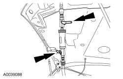
- Install the dye/lubricant injector between the low-pressure service gauge port valve and the R-134a Refrigerant Management Machine or R-134a Manifold Gauge Set.
- NOTE:
Following fluorescent dye injection, the refrigerant system should be fully charged to make sure of correct movement of the dye.
Open all valves and inject the fluorescent dye into the refrigerant system by charging the refrigerant system with the required amount of R-134a.
- When fluorescent dye injection is complete, close all valves.
- Recover the refrigerant from the dye/lubricant injector.
- Remove the dye/lubricant injector from the low-pressure service gauge port valve and the R-134a Refrigerant Management Machine or R-134a Manifold Gauge Set.
Fluorescent Dye Injection Using a R-134a Loop/Add On Injector Kit-Set — Vehicles Not Requiring R-134a Addition
NOTE:
Fluorescent refrigerant system dye is added to the refrigerant system at the factory to assist in refrigerant system leak diagnosis using a Rotunda-approved UV blacklight. It is not necessary to add additional dye to the refrigerant system before diagnosing leaks, even if a significant amount of refrigerant has been removed from the system. Replacement suction accumulators and receiver/driers are shipped with a fluorescent dye "wafer" included in the desiccant bag which will dissolve after approximately 30 minutes of continued A/C operation. It is not necessary to add dye after flushing or filtering the refrigerant system because a new suction accumulator or receiver/drier is installed as part of the flushing or filtering procedure. Additional refrigerant system dye should only be added if more than 50% of the refrigerant system lubricant capacity has been lost due to a fitting separation, hose rupture or other damage.
NOTE:
Before using the R-134a Loop/Add On Injector Kit-Set for the first time, refer to the equipment manufacturer's instructions on evacuation of non-condensable gases from the hoses.
NOTE:
Refrigerant system pressure should be between 413-551 kPa (60-80 psi) at 24°C (75°F) with the engine off and cool.
- Verify that the valves on the R-134a Loop/Add On Injector Kit-Set are closed.
- Fill the R-134a Loop/Add On Injector Kit-Set reservoir with 7 ml (0.25 oz) of fluorescent dye.
- Install the R-134a Loop/Add On Injector Kit-Set between the high-pressure and low-pressure service gauge port valves.
- NOTICE: Make sure all tools and hoses are clear of the engine cooling
fan and drive belt before starting the engine. Failure to keep tools and hoses
clear from the engine cooling fan and drive belt will result in damage to the
tools and/or vehicle.
With the A/C off, start the engine. Allow engine speed to stabilize below 1,000 rpm.
- Set the A/C to the ON position.
- Open the high-pressure service valve.
- NOTE:
To prevent pressure spike/liquid slug, crack the R-134a Loop/Add On Injector Kit-Set valves and slowly open to inject the fluorescent dye into the refrigerant system.
Open the R-134a Loop/Add On Injector Kit-Set valves and inject the fluorescent dye into the refrigerant system.
- Close the high-pressure service valve to allow the pressure inside the R-134a Loop/Add On Injector Kit-Set to equalize with the suction side of the refrigerant system.
- NOTE:
Close the valves on the R-134a Loop/Add On Injector Kit-Set while the A/C compressor is operating.
Close the valves on the R-134a Loop/Add On Injector Kit-Set.
- NOTE:
Leave all valves on the R-134a Loop/Add On Injector Kit-Set closed when not in use.
Disconnect the high-pressure and low-pressure service valves and remove the R-134a Loop/Add On Injector Kit-Set from the vehicle.
Fluorescent Dye Detection
NOTE:
Ford Motor Company vehicles are produced with R-134a fluorescent dye installed in the refrigerant system from the factory. The location of leaks can be pinpointed by the bright yellow-green glow of the fluorescent dye under a UV lamp. Since more than one leak can exist, make sure to inspect each component, line and fitting in the refrigerant system for a leak.
NOTE:
Use of dye-enhancing glasses or goggles greatly improves the detection of the dye under the UV lamp.
NOTE:
Not all UV lamps will fluoresce the dye used in Ford vehicles. All Rotunda UV lamps are optimized to fluoresce the dye.
- Check for leaks using a Rotunda-approved UV lamp and dye enhancing glasses.
- Inspect all components, lines and fittings of the refrigerant system.
- After the leak(s) is repaired, remove any traces of fluorescent dye with a general purpose oil solvent.
- Verify the repair by running the vehicle for a short period of time and rechecking the area of the leak with a Rotunda-approved UV lamp.
 Air Conditioning - Description and Operation
The refrigerant system components include the following:
A/C compressor and clutch assembly
A/C condenser core
A/C evaporator core
Receiver/drier
Connecting refrigerant lines
Therm ...
 Refrigerant Identification Testing
Special Tool(s)
Refrigerant Blend Identifier with Printer
198-00012 or equivalent
Refrigerant Identification
NOTE: A Refrigerant Blend Identifier with Printer mus ...
More about Ford Focus:
Ford Focus Telephone setup
Phonebook
Note: It may be necessary to confirm
phonebook access to the Bluetooth
system via the mobile phone.
After start up access to the phonebook
list can be delayed for several minutes,
depending upon the size.
Phonebook categories
Depending on your phonebook entry,
different categories ...
Nissan Frontier - Instrument Panel - Keys - Brake system
