Ford Focus Service Manual: Air Conditioning - Description and Operation
The refrigerant system components include the following:
- A/C compressor and clutch assembly
- A/C condenser core
- A/C evaporator core
- Receiver/drier
- Connecting refrigerant lines
- Thermostatic Expansion Valve (TXV)
The refrigerant system incorporates an A/C compressor controlled by the PCM through an A/C clutch relay. The HVAC module sends an A/C request signal to the Instrument Cluster (IC) , which relays the request to the PCM. An evaporator discharge air temperature sensor is used to cycle the A/C compressor off when the evaporator core temperature falls below an acceptable temperature.
The HVAC module will send an A/C request signal to the instrument cluster if the following conditions are met:
- A mode which requires A/C operation has been manually selected by the driver.
- The A/C evaporator discharge air temperature sensor is reading an acceptable temperature.
When an A/C request is received, the A/C compressor clutch will only be engaged by the PCM through the A/C clutch relay if all of the following conditions are met:
- The A/C pressure transducer is reading an acceptable pressure in the high-pressure side of the refrigerant system.
- The engine coolant temperature is not excessively high.
- The PCM has not detected a Wide Open Throttle (WOT) condition.
An A/C compressor pressure relief valve is installed in the A/C compressor to protect the refrigerant system against excessively high refrigerant pressures.
A/C Compressor and Clutch Assembly
NOTE:
Internal A/C compressor components are not serviced separately. The A/C compressor, minus the A/C compressor clutch and field coil, is serviced as an assembly. A new A/C pressure relief is included with replacement A/C compressors, but the valve is also available as a separate component and can be independently replaced if needed. The A/C compressor clutch, A/C compressor pulley and A/C clutch field coil are serviceable as a separate assembly.
The A/C compressor has the following characteristics:
- A non-serviceable shaft seal.
- The A/C compressor uses PAG Refrigerant Compressor Oil (R-134a Systems) YN-12-D. This oil contains special additives required for the A/C compressor.
- The A/C compressor oil in the A/C system may darken over time while maintaining normal oil viscosity. This is normal for A/C systems because of break-in wear.
- Use the refrigerant oil adding procedure specified for this vehicle when installing a new A/C compressor or any other A/C component. Refer to the Refrigerant Oil Adding procedure in Section 412-00.
When battery voltage is applied to the A/C compressor clutch field coil, the clutch disc and hub assembly is drawn toward the A/C clutch pulley. The magnetic force locks the clutch plate and hub assembly and the A/C clutch pulley together as one unit, causing the compressor shaft to rotate with the engine. When battery voltage is removed from the A/C compressor clutch field coil, springs in the clutch plate and hub assembly move the clutch plate away from the A/C clutch pulley.
An A/C clutch diode is included for A/C clutch field coil circuit spike suppression. The A/C clutch diode is located in the Battery Junction Box (BJB) .
A/C Pressure Relief Valve
NOTE:
If the A/C compressor is operating within limits and the A/C pressure relief valve is venting, or if the A/C pressure relief valve is leaking around the threads, install a new A/C pressure relief valve and O-ring. If the new A/C pressure relief valve still vents after it is installed, diagnose the refrigerant system for a restriction.
An A/C pressure relief valve is incorporated in the A/C compressor to prevent damage to the A/C compressor and other system components by relieving unusually high system discharge pressure buildups. For specifications regarding operating pressure(s), refer to Section 412-00.
The A/C pressure relief valve is a separate component and can be installed separately from the A/C compressor. It is necessary to recover the refrigerant before removing the A/C pressure relief valve.
A/C Condenser Core
The A/C condenser is an aluminum fin-and-tube design heat exchanger located in front of the vehicle radiator. It cools compressed refrigerant gas by allowing air to pass over fins and tubes to extract heat, and condenses gas to liquid refrigerant as it is cooled.
A/C Evaporator Core
NOTE:
The evaporator core is not separately serviceable, it is serviced only with the evaporator core housing assembly.
The evaporator core is an aluminum plate/fin type and is located in the heater core and evaporator core housing. A mixture of liquid refrigerant and oil enters the bottom of the evaporator core through the evaporator core inlet tube and continues out of the evaporator core through the evaporator core outlet tube as a vapor. During A/C compressor operation, airflow from the blower motor is cooled and dehumidified as it flows through the evaporator core fins.
Thermostatic Expansion Valve (TXV)
The Thermostatic Expansion Valve (TXV) is located at the evaporator core inlet and outlet tubes at the center rear of the engine compartment. The TXV provides a restriction to the flow of refrigerant from the high-pressure side of the refrigerant system and separates the low-pressure and high-pressure sides of the refrigerant system. Refrigerant entering and exiting the evaporator core passes through the TXV through 2 separate flow paths. An internal temperature sensing bulb senses the temperature of the refrigerant flowing out of the evaporator core and adjusts an internal pin-type valve to meter the refrigerant flow into the evaporator core. The internal pin-type valve decreases the amount of refrigerant entering the evaporator core at lower temperatures and increases the amount of refrigerant entering the evaporator core at higher temperatures.
Receiver/Drier
NOTE:
Installation of a new receiver/drier is not required when repairing the A/C system, except when there is physical evidence of contamination from a failed A/C compressor or damage to the receiver/drier. Damage to the receiver/drier includes leaks, physical damage to the receiver/drier shell or desiccant, or moisture contamination. Moisture contamination results only from a complete loss of refrigerant, and equalization of the refrigerant system pressure with atmospheric pressure for a period longer than one hour. If even a slight amount of positive refrigerant pressure is present in the refrigerant system before repairs are carried out, a new receiver/drier should not be installed.
The receiver/drier is mounted to the LH front of the condenser core. It stores high-pressure liquid after it leaves the condenser core. A desiccant cartridge mounted inside the receiver/drier removes moisture from the refrigerant.
A/C Evaporator Discharge Air Temperature Sensor
The A/C evaporator discharge air temperature sensor contains a thermistor which receives a reference voltage from the HVAC module. The thermistor then varies the resistance to the reference voltage based on the evaporator discharge air temperature. The HVAC module interprets this resistance as the evaporator discharge air temperature.
The A/C evaporator discharge air temperature sensor is located on the RH side of the heater core and evaporator core housing above the heater core tube cover.
A/C Pressure Transducer
The A/C pressure transducer monitors the compressor discharge pressure and communicates with the PCM. The PCM will interrupt A/C compressor operation in the event that the A/C pressure transducer indicates high system discharge pressures. It is also used to sense low charge conditions. If the pressure is below a predetermined value for a given ambient temperature, the PCM will not allow the clutch to engage.
The A/C pressure transducer is located on the condenser-to-evaporator line near the RH shock tower. It is not necessary to recover the refrigerant before removing the A/C pressure transducer.
Service Gauge Port Valves
The high-pressure service gauge port valve is located on a vertical extension off the receiver/drier tank. The valve can be accessed through an access hole in the upper radiator air deflector to the right of the LH headlamp.
The low-pressure service gauge port valve is located on the A/C compressor suction line near the RH shock tower.
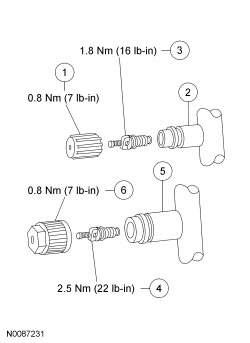
| Item | Part Number | Description |
|---|---|---|
| 1 | 19D702 | A/C charging valve cap |
| 2 | — | Low-pressure service gauge port valve |
| 3 | 19D701 | Low-pressure Schrader-type valve |
| 4 | 19D701 | High-pressure Schrader-type valve |
| 5 | — | High-pressure service gauge port valve |
| 6 | 19D702 | A/C charging valve cap |
The fitting is an integral part of the refrigerant system line or component.
- Special couplings are required for both the high-side and low-side service gauge ports.
- A very small amount of leakage will always be detectable around the Schrader-type valve with the service gauge port valve cap removed, and is considered normal. A new Schrader-type valve core can be installed if the seal leaks excessively.
- The service gauge port valve caps each include an O-ring seal which is used as a primary seal in the refrigerant system to prevent leakage through the Schrader-type valves from reaching the atmosphere. The service gauge port valve cap O-ring seals should be checked when checking the refrigerant system for leaks and a new cap should be installed if needed. Always install and tighten the A/C service gauge port valve caps to the correct torque after they are removed.
Refrigerant System Dye
Fluorescent refrigerant system dye is added to the refrigerant system at the factory to assist in refrigerant system leak diagnosis using a Rotunda-approved ultraviolet black light. It is not necessary to add additional dye to the refrigerant system before diagnosing leaks, even if a significant amount of refrigerant has been removed from the system. Replacement receiver/driers are shipped with a fluorescent dye "wafer" included in the desiccant bag, which will dissolve after approximately 30 minutes of continued A/C operation. It is not necessary to add dye after flushing or filtering the refrigerant system because a new receiver/drier is installed as part of the flushing or filtering procedure. Additional refrigerant system dye should only be added if more than 50% of the refrigerant system lubricant capacity has been lost due to a fitting separation or hose rupture. Refer to Section 412-00.
 Air Conditioning (A_C) System Recovery, Evacuation and Charging
Special Tool(s)
6.0 CFM Vacuum Pump
300-R0B15600E or equivalent
Automatic Refrigerant Charging Meter
023-00155 or equivalent
R- ...
 Fluorescent Dye Leak Detection
Special Tool(s)
Cordless/Rechargeable True UV LED Light ES
023-00182 or equivalent
R-134a Loop/Add On Injector Kit-Set
219-00069 or equivalent
...
More about Ford Focus:
Ford Focus Battery and Cables
Vehicles are equipped with a 12-volt, maintenance-free battery.
The battery and cable system consists of the following components:
Battery
Battery cable assembly
Battery tray
The battery is a 12V DC source connected in a negative ground system. The battery
case is sealed with 2 ve ...
Nissan Frontier - Instrument Panel - Keys - Brake system
