Ford Focus Service Manual: Instrument Panel and Console
Removal
Automatic transmission
- Remove the selector lever. For additional information, refer to Section
307-05.
Manual transmission
- Remove the gearshift lever. For additional information, refer to Section
308-06.
All vehicles
- Depower the Supplemental Restraint System (SRS) . For additional information, refer to Section 501-20B.
- Remove the SRS module.
- Remove the 3 SRS module bolts.
- Disconnect the electrical connectors.
- Disconnect the park brake lever electrical connector.
- Remove the 3 wire harness pin-type retainers.
- Remove the LH and RH A-pillar trim panels and front scuff plate trim panels. For additional information, refer to Section 501-05.
- Remove the RH and LH lower cowl trim panels.
- Remove the 4 lower cowl trim panel retainers.
- Remove the hood release handle.
- Remove the hood release handle bolt.
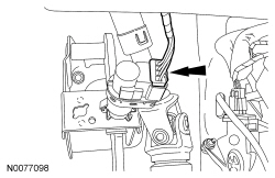
- Rotate the steering wheel to gain access to the upper steering column shaft-to-lower steering column shaft bolt.
- Remove and discard the upper steering column shaft-to-lower steering column shaft bolt.
- Rotate the steering wheel until the front wheels are in the straight-ahead position.
- Remove the steering wheel. For additional information, refer to Section 211-04.
- Detach the upper steering column shaft from the lower steering column shaft.
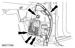
- Remove the ground wire bolt and disconnect the 3 electrical connectors and the antenna cable located at the RH lower cowl.
- Disconnect the blower motor electrical connector.
- Remove the wire harness pin-type retainer from the heater core and evaporator core housing.
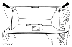
- Lower the glove compartment door.
- Open the glove compartment door.
- Press the 2 glove compartment door retaining tabs and fully lower the glove compartment door.
- Disconnect the electrical connector located on the heater core and evaporator core housing.
- Close the glove compartment door.
- Lift upward on the glove compartment door.
- Press the 2 glove compartment door retaining tabs and fully close the glove compartment door.
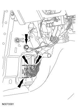
- Disconnect the Brake Pedal Position (BPP) sensor electrical connector.
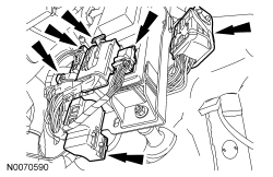
- Disconnect the 5 Smart Junction Box (SJB) electrical connectors and the LH bulkhead electrical connector.
- Remove the lower ground wire bolt and disconnect the 3 electrical connectors at the LH lower cowl.
- Remove the LH instrument panel side bolt cover.
- Remove the LH instrument panel side bolt.
- Remove the instrument panel upper cowl cover.
- NOTICE: When removing the instrument panel upper bolt, care must be taken
to prevent damage to the windshield.
Remove the instrument panel upper cowl bolt.
- Remove the LH and RH rear footwell duct connector pushpin retainers.
- Remove the 6 LH and RH instrument panel support bracket bolts.
- Remove the LH and RH instrument panel support brackets.
- Remove the rear footwell duct extension.
- Remove the 6 LH and RH instrument panel bolts.
- NOTICE: To avoid damage to the instrument panel, an assistant is required
when carrying out this step.
Remove the instrument panel.
- Transfer parts as needed.
Installation
All vehicles
- NOTICE: To avoid damage to the instrument panel, an assistant is required
when carrying out this step.
NOTE:
Make sure that all electrical connectors and wiring are correctly routed when installing the instrument panel.
Install the instrument panel.- Install, but do not tighten, the 6 instrument panel side bolts.
- NOTICE: When installing the instrument panel upper bolt, care must be
taken to prevent damage to the windshield.
Install the instrument panel upper cowl bolt.
- Tighten to 9 Nm (80 lb-in).
- Install the instrument panel upper cowl bolt cover.
- Install the LH instrument panel side bolt.
- Tighten to 25 Nm (18 lb-ft).
- Install the LH instrument panel side bolt cover.
- Tighten the 6 LH and RH instrument panel bolts.
- Tighten to 25 Nm (18 lb-ft).
- Install the rear footwell duct extension.
- Install the LH and RH instrument panel support brackets.
- Install the 6 LH and RH instrument panel support bracket bolts.
- Tighten to 25 Nm (18 lb-ft).
- Install the LH and RH rear footwell duct connector pushpin retainers.
- Install the lower ground wire and bolt at the LH lower cowl.
- Tighten to 10 Nm (89 lb-in).
- Connect the 3 electrical connectors at the LH lower cowl.
- Connect the 5 SJB electrical connectors and the LH bulkhead electrical connector.
- Connect the BPP sensor electrical connector.
- Lower the glove compartment door.
- Open the glove compartment door.
- Press the 2 glove compartment door retaining tabs and fully lower the glove compartment door.
- Connect the electrical connector located on the heater core and evaporator core housing.
- Close the glove compartment door.
- Lift upward on the glove compartment door.
- Press the 2 glove compartment door retaining tabs and fully close the glove compartment door.
- Connect the blower motor electrical connector.
- Install the wire harness pin-type retainer onto the heater core and evaporator core housing.
- Install the ground wire and bolt located at the RH lower cowl.
- Tighten to 10 Nm (89 lb-in).
- Connect the 3 electrical connectors and the antenna cable located at the RH lower cowl.
- Install the upper steering column shaft onto the lower steering column shaft.
- Install the steering wheel. For additional information, refer to Section 211-04.
- Install a new upper steering column shaft-to-lower steering column shaft
bolt.
- Tighten to 28 Nm (21 lb-ft).
- Install the hood release handle.
- Install the hood release handle bolt.
- Install the RH and LH lower cowl trim panels.
- Install the 4 lower cowl trim panel retainers.
- Install the LH and RH A-pillar trim panels and front scuff plate trim panels. For additional information, refer to Section 501-05.
- Install the 3 wire harness pin-type retainers.
- Connect the park brake lever electrical connector.
- Install the SRS module.
- Install the 3 SRS module bolts.
- Connect the electrical connectors.
- Repower the SRS . For additional information, refer to Section 501-20B.
Manual transmission
- Install the gearshift lever. For additional information, refer to Section
308-06.
Automatic transmission
- Install the selector lever. For additional information, refer to Section 307-05.
 Console - Floor
Item
Part Number
Description
1
04567
Floor console finish panel
2
W707938
Floor console rear screws (2 required)
3
672A40
Flo ...
 Power Point
Special Tool(s)
Remover, Power Point Socket
501-039 or equivalent
Removal
NOTE: Power point cover may differ depending on location.
Open the power point cover. ...
More about Ford Focus:
Ford Focus Safety Belt Buckle - Rear
Item
Part Number
Description
1
60044
Safety belt buckle assembly
2
—
Safety belt buckle bolt (part of 60044)
Removal and Installation
WARNING: After
any crash, all of the following safety belt assemblies and attaching hardware ...
© 2016-2026 Copyright www.ffguide.net
