Ford Focus Service Manual: Refrigerant Oil Adding

|
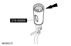
R-134a Loop/Add On Injector Kit-Set 219-00069 or equivalent |
| Item | Specification |
|---|---|
| Motorcraft® PAG Refrigerant Compressor Oil YN-12-D | WSH-M1C231-B |
Refrigerant Oil Adding
NOTE:
During normal A/C operation, oil is circulated through the system with the refrigerant, and a small amount is retained in each component. If certain components of the system are removed, some of the PAG oil will go with the component. To maintain the original total oil charge, it is necessary to compensate for the oil lost by adding oil to the system with the new part.
- Refer to the chart below for refrigerant oil adding amounts and methods
of installation.
Component PAG Oil Amount Method of Adding A/C Compressor Refer to Adding Refrigerant Oil After A/C Compressor Replacement Add or remove directly through A/C compressor low-side port before installation. Suction Accumulator or Receiver/Drier Refer to Adding Refrigerant Oil After New Suction Accumulator or Receiver/Drier Replacement Add directly to suction accumulator inlet port or inject to low-side service port during system charging. Evaporator Core 45 ml (1.5 fl oz) added to the amount collected during refrigerant recovery Add directly to evaporator core inlet tube or inject to low-side service port during system charging. Condenser Core 60 ml (2 fl oz) added to the amount collected during refrigerant recovery Add directly to condenser core inlet or inject to low-side service port during system charging. Evaporator Core Orifice or Thermostatic Expansion Valve (TXV) The amount collected during refrigerant recovery Inject to low-side service port during system charging. A/C Pressure Relief Valve 60 ml (2 fl oz) added to the amount collected during refrigerant recovery Inject to low-side service port during system charging. Refrigerant Hose/Line 60 ml (2 fl oz) added to the amount collected during refrigerant recovery a Inject to low-side service port during system charging. O-ring Leak Repair 60 ml (2 fl oz) added to the amount collected during refrigerant recovery b Inject to low-side service port during system charging. Service Port Leak Repair 60 ml (2 fl oz) added to the amount collected during refrigerant recovery Inject to low-side service port during system charging.
aIf an excessive amount of PAG oil is lost due to a hose rupture/separation or other damage, the total system PAG oil capacity must be added.
bThe amount specified may be used for one or multiple O-ring leak repairs. Do not multiply the PAG oil amount by the number of O-ring leaks being repaired.
Adding Refrigerant Oil After A/C Compressor Replacement
Service A/C compressors shipped without clutch and pulley
- Rotate the old A/C compressor shaft 6 to 8 revolutions while collecting
oil in a clean measuring device.
- If the amount of oil drained from the old A/C compressor is between 85-142 ml (3-5 oz), pour the same amount plus 30 ml (1 oz) of clean PAG Refrigerant Compressor Oil (R-134a Systems) (YN-12-D) WSH M1C231-B or equivalent into the new A/C compressor.
- If the amount of oil that was removed from the old A/C compressor is greater than 142 ml (5 oz), pour the same amount drained of clean PAG Refrigerant Compressor Oil (R-134a Systems) or equivalent into the new A/C compressor.
- If the amount of oil that was removed from the old A/C compressor is less than 85 ml (3 oz), pour 85 ml (3 oz) of clean A/C Refrigerant Compressor Oil (R-134a Systems) or equivalent into the new A/C compressor.
Service A/C compressors shipped with clutch and pulley
- Rotate the old A/C compressor shaft 6 to 8 revolutions while collecting
oil in a clean measuring device.
- If the amount of oil drained from the old A/C compressor is less than 89 ml (3 oz), remove 118 ml (4 oz) from the new A/C compressor.
- If the amount of oil drained from the old A/C compressor is 89 ml (3 oz), remove 89 ml (3 oz) from the new A/C compressor.
- If the amount of oil drained from the old A/C compressor is 118 ml (4 oz), remove 59 ml (2 oz) from the new A/C compressor.
- If the amount of oil drained from the old A/C compressor is 148 ml (5 oz), remove 29 ml (1 oz) from the new A/C compressor.
- If the amount of oil drained from the old A/C compressor is greater than 148 ml (5 oz), remove 0 ml (0 oz) from the new A/C compressor.
Adding Refrigerant Oil After New Suction Accumulator or Receiver/Drier Replacement
NOTE:
This refrigerant oil adding method is to be used when a new suction accumulator or receiver drier only has been installed. If a new A/C compressor and evaporator core orifice or Thermostatic Expansion Valve (TXV) have also been installed due to system contamination, refer to the appropriate heading.
- Drill one 12.7 mm (1/2 in) hole in the old suction accumulator or receiver/drier cylinder and drain the oil into a clean measuring cup.
- Add the same quantity of new PAG oil, plus the amount collected during refrigerant recovery and 60 ml (2 fl oz).
Adding Refrigerant Oil After Multiple Component Replacement After A/C System Contamination
NOTE:
This refrigerant oil adding method is to be used when a new A/C compressor, suction accumulator or receiver drier and evaporator core orifice or TXV have been installed due to system contamination and the A/C system has been flushed.
- If the new A/C compressor is shipped with a new clutch and pulley already installed, remove the shipping caps and rotate the new A/C compressor shaft 6 to 8 revolutions while collecting the oil in a clean measuring cup.
- Add 60 ml (2 fl oz) directly to the new A/C compressor suction port.
- Inject the total vehicle PAG oil capacity minus 60 ml (2 fl oz) to the low-side service port during system charging. For the total PAG oil capacity specification, refer to the Specifications table in this section.
Oil Injection Using a Dye/Lubricant Injector
NOTE:
If fluorescent leak detection dye is also to be added during A/C charging, the dye may be added to the dye/lubricant injector, from the R-134a Loop/Add On Injector Kit-Set, along with the PAG oil.
- Evacuate the refrigerant system. For additional information, refer to Air Conditioning (A/C) System Recovery, Evacuation and Charging in this section.
- Assemble the dye/lubricant injector and the correct adapters from the R-134a Loop/Add On Injector Kit-Set to match the amount of refrigerant compressor oil to be injected.
- Verify that all the valves on the dye/lubricant injector are closed.
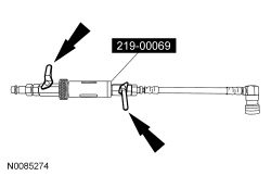
- Fill the dye/lubricant injector with the correct amount of clean, new PAG oil.
- Install the dye/lubricant injector between the low-side service gauge port valve and the refrigerant service station or manifold gauge set.
- Open all valves and charge the refrigerant system. For additional information, refer to Air Conditioning (A/C) System Recovery, Evacuation and Charging in this section.
 Refrigerant Identification Testing
Special Tool(s)
Refrigerant Blend Identifier with Printer
198-00012 or equivalent
Refrigerant Identification
NOTE: A Refrigerant Blend Identifier with Printer mus ...
 Refrigerant System Tests
Special Tool(s)
R-134a Manifold Gauge Set
023-00047 or equivalent
R-134a Refrigerant Management Machine (SAE J-2788 Compliant)
023-00181 or equivalen ...
More about Ford Focus:
Ford Focus Roof Opening Panel Motor Initialization
WARNING: Keep objects
and body parts clear of the glass panel when carrying out the initialization procedure.
During the initialization procedure, the glass panel closes with high force and
cannot detect objects in its path. Failure to follow this instruction may result
in serious personal i ...
Nissan Frontier - Instrument Panel - Keys - Brake system
