Ford Focus Service Manual: Restraints Control Module (RCM)

|
Vehicle Communication Module (VCM) and Integrated Diagnostic System
(IDS) software with appropriate hardware, or equivalent scan tool |
| Item | Part Number | Description |
|---|---|---|
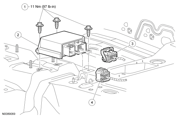
| 1 | W704265 | Restraints Control Module (RCM) bolts (3 required) |
| 2 | 14B321 | RCM |
| 3 | — | Large RCM electrical connector (part of 14A005) |
| 4 | — | Small RCM electrical connector (part of 14401) |
Removal
 WARNING: If a vehicle
has been in a crash, inspect the restraints control module (RCM) and the impact
sensor (if equipped) mounting areas for deformation. If damaged, restore the mounting
areas to the original production configuration. A new RCM and sensors must be installed
whether or not the airbags have deployed. Failure to follow these instructions may
result in serious personal injury or death in a crash.
WARNING: Do not
handle, move or change the original horizontal mounting position of the restraints
control module (RCM) while the RCM is connected and the ignition switch is ON. Failure
to follow this instruction may result in the accidental deployment of the Safety
Canopy and cause serious personal injury or death.
NOTE:
The air bag warning indicator illuminates when the correct Restraints Control Module (RCM) fuse is removed and the ignition is ON.
NOTE:
The Supplemental Restraint System (SRS) must be fully operational and free of faults before releasing the vehicle to the customer.
NOTE:
Carrying out Programmable Module Installation (PMI) will not enable the 911 assist option that is disabled. The RCM and Accessory Protocol Interface Module (APIM) must be configured correctly to fully support 911 assist functionality.
- When installing a new RCM , carry out the appropriate steps necessary for the Programmable Module Installation (PMI) procedure. For additional information, refer to Section 418-01.
- Depower the SRS . For additional information, refer to Supplemental Restraint System (SRS) Depowering and Repowering in the General Procedures portion of this section.
- Remove the center console. For additional information, refer to Section 501-12.
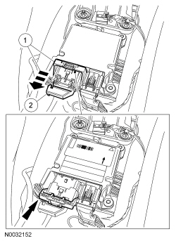
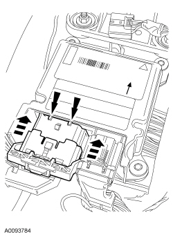
- Disconnect the large RCM electrical connector.
- Pinch the thumb tab and pivot the connector position assurance lever all the way back until it stops.
- Pull out and disconnect the large RCM electrical connector.
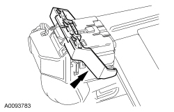
- Disconnect the small RCM electrical connector.
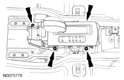
- If equipped with an automatic transmission, remove the 4 nuts and position the gear selector aside.
- Remove the 3 bolts and RCM .
Installation
- WARNING: Always
tighten the fasteners of the restraints control module (RCM) and impact sensor (if equipped) to the specified torque. Failure to do so may result in incorrect restraint system operation, which increases the risk of personal injury or death in a crash.Install the RCM and 3 bolts.
- Tighten to 11 Nm (97 lb-in).
- If equipped with an automatic transmission, install the gear selector and
4 nuts.
- Tighten to 9 Nm (80 lb-in).
- Connect the small RCM electrical connector.
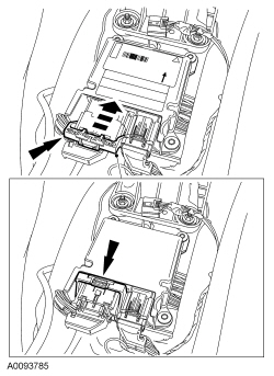
- Make sure the large RCM electrical connector position assurance lever is in the FULL RELEASE position before attempting to connect the connector.
- NOTICE: Placing the large Restraints Control Module (RCM) electrical
wiring connector into the RCM at an angle can cause bad electrical connections
and damage components.
Position the large RCM electrical wiring connector into the RCM .
- NOTICE: Do not push the connector to where the lever pivots and seats
itself. Light pressure is needed to get the connector into position on the
Restraints Control Module (RCM) before using the lever to fully seat the
connector.
With the large RCM electrical wiring connector uniformly aligned to the RCM , lightly push in until a subtle audible click is heard and a slight resistance is felt.
- NOTICE: Do not push the connector to where the lever pivots and seats
itself. Light pressure is needed to get the connector into position on the
Restraints Control Module (RCM) before using the lever to fully seat the
connector.
- Connect the large RCM electrical wiring connector.
- Using the connector position assurance lever, pivot it toward the RCM
, drawing the connector into the RCM .
- Make sure the thumb tab is engaged to the retainer on the RCM and locked in place.
- Using the connector position assurance lever, pivot it toward the RCM
, drawing the connector into the RCM .
- Install the center console. For additional information, refer to Section 501-12.
- Repower the SRS . Do not prove out the SRS at this time.
For additional information, refer to Supplemental Restraint System (SRS) Depowering and Repowering in the General Procedures portion of this section.
- If a new RCM was installed, carry out the appropriate steps to complete the Programmable Module Installation (PMI) procedure. For additional information, refer to Section 418-01.
- Prove out the SRS as follows:
Turn the ignition from ON to OFF. Wait 10 seconds, then turn the ignition back
to ON and monitor the air bag indicator with the air bag modules installed.
The air bag warning indicator will light continuously for approximately 6 seconds
and then turn OFF. If an air bag SRS fault is present, the air bag indicator
will:
— fail to light.
— remain lit continuously. — flash at a 5 Hz rate (RCM not configured). The air bag warning indicator might not light until approximately 30 seconds after the ignition has been turned from the OFF to the ON position. This is the time required for the RCM to complete the testing of the SRS . If the air bag indicator is inoperative and a SRS fault exists, a chime will sound in a pattern of 5 sets of 5 beeps. If this occurs, the air bag indicator and any SRS fault discovered must be diagnosed and repaired. Clear all continuous DTCs from the RCM and Occupant Classification System Module (OCSM) .

 Front Impact Severity Sensor
Item
Part Number
Description
1
W712191
Front impact severity sensor bolt
2
14B006
Front impact severity sensor
3
—
Front im ...
More about Ford Focus:
Ford Focus Heated windows and mirrors
Heated windows
Use the heated windows to defrost or
demist the windscreen or rear window.
Note: The heated windows operate only
when the engine is running.
Heated windscreen
Note: Also defrosts the front washer jets.
Heated rear window
Heated exterior mirrors
Electric exterior mirro ...
Nissan Frontier - Instrument Panel - Keys - Brake system
