Ford Focus Service Manual: Transaxle - Disassembly (Automatic Transaxle/Transmission — 4F27E)

|
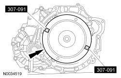
Handle, Torque Converter 307-091 (T81P-7902-C) |

|
Holding Tool, Final Drive Input Gear 307-413 |

|
Mounting Bracket, Transmission 307-410 |

|
Puller, Bearing 205-D064 (D84L-1123-A) or equivalent |

|
Remover/Installer, Front Wheel Hub 204-069 (T81P-1104-C) |

|
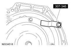
Retainer, Torque Converter 307-346 (T94T-7902-A) |

|
Socket, Final Drive Input Nut 307-414 |

|
Step Plate 205-D015 (T80L-630-4) or equivalent |

|
Wrench Guide Plate 307-420 |
| Item | Specification |
|---|---|
| Motorcraft® MERCON® LV Automatic Transmission Fluid XT-10-QLVC (US); CXT-10-LV12 (Canada) | MERCON® LV |
| Motorcraft® Metal Surface Prep ZC-31-A | — |
Disassembly
- NOTICE: If, during repair work, abrasive particles are found in the transmission
fluid (particles from the clutch or metal chips or foreign material), the transaxle
must be disassembled completely and thoroughly cleaned. Also, clean the transmission
fluid cooler tubes, transmission fluid cooler and torque converter carefully.
In the case of extreme contamination of the transmission fluid cooler tubes,
install a new fluid cooler and torque converter.
NOTE:
In case of clutch abrasion, rinse the torque converter with transmission fluid.
Inspect the transaxle during disassembly.
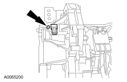
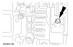
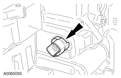
- Remove the OSS sensor in the following sequence.
- Remove the bolt.
- Remove the OSS sensor.
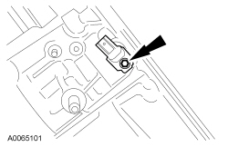
- Remove the TSS sensor.
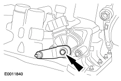
- NOTICE: Do not use air tools or damage to the transaxle manual control
valve internal linkage can occur.
While holding the manual control lever, remove the manual control lever bolt.
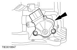
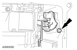
- Remove the TR sensor.
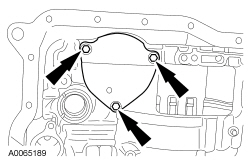
- Remove the Torque Converter Retainer.
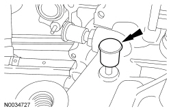
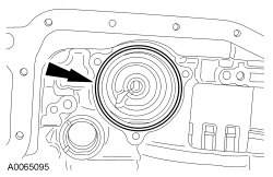
- Remove the rubber vent cap.
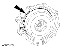
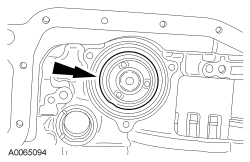
- NOTICE: Do not tilt the torque converter when removing it, to prevent
damaging the torque converter hub.
NOTE:
The torque converter is filled with transmission fluid. Drain the torque converter.
Using the Torque Converter Handles, remove the torque converter.
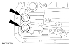
- Remove the differential opening cover.
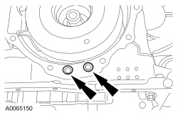
- Remove the LH and RH axle seals.
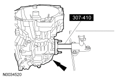
- Using the Transmission Mounting Bracket, mount the transaxle to a bench.
- Remove the bolts.
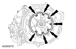
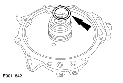
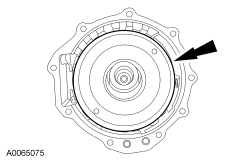
- Using the two 10 mm (0.393 in) (50 mm [1.968 in] long) bolts, remove the pump.
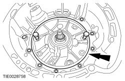
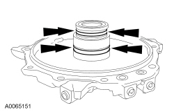
- Remove the transmission pump seals.
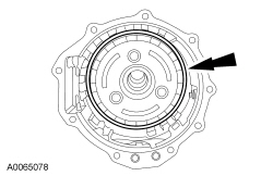
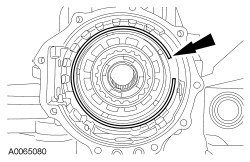
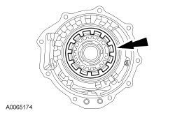
- Remove the forward clutch thrust washer.
- Remove the forward clutch assembly.
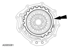
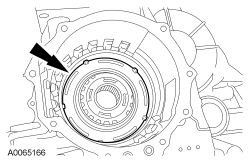
- NOTE:
Small levers will aid in the removal of the forward clutch hub.
Remove the forward clutch hub.
- Rotate the transaxle 180 degrees.
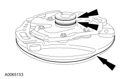
- Remove the end cover.
- Clean the silicone from the end cover and transaxle case surfaces thoroughly with metal surface prep.
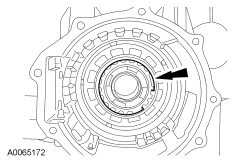
- Remove the direct clutch hub bearing shim.
- Remove the end cover seals.
- Remove the end cover-to-case seals.
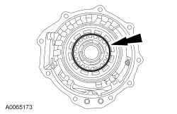
- Remove the direct clutch cylinder thrust bearing.
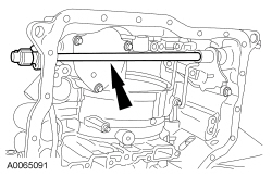
- Remove the intermediate/O/D band anchor bolt.
- Remove the intermediate/O/D band.
- Remove the intermediate/O/D drum assembly.
- Remove the planet gear assembly.
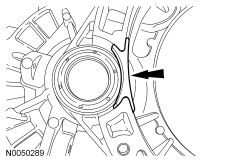
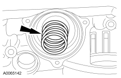
- Remove the low/reverse clutch plate retaining ring.
- Remove the low/reverse clutch plates, pressure plate and wave spring.
- Remove the low OWC retaining ring.
- Remove the low OWC inner race.
- Remove the low/reverse clutch return spring.
- Remove the low/reverse clutch piston.
- Remove the transmission fluid pan.
- Remove the bolts.
- Remove the transmission fluid pan.
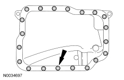
- Clean the silicone from the transmission fluid pan and transaxle case surfaces thoroughly with metal surface prep.
- Disconnect the TFT sensor.
- Remove the transmission fluid filter.
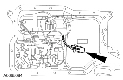
- NOTE:
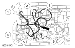
It is necessary to note the location of the main control wire harness connectors so they can be connected in the same positions. Connector color letters are cast into the solenoid body.
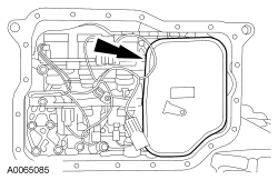
Remove the main control ground wire bolt, disconnect the electrical connectors and remove the wire harness.
- SSC , color N (White)
- SSE , color G (Green)
- SSD , color L (Blue)
- LPC , color B (Black)
- SSA , color N (Natural)
- SSB , color B (Black)
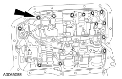
- NOTE:
Note the locations of the longer bolts.
Remove the 13 main control valve body bolts.
- NOTE:
Squeeze the tabs on the side of the electrical connector.
Remove the transaxle internal harness electrical connector.
- NOTE:
Each accumulator piston has 2 springs inside of them, totaling 4 springs. All 4 springs are different sizes. The accumulator piston bore and accumulator pistons are a match as to depth. Some of the accumulator pistons may have steps. Take note of the size, depth and location of the accumulator pistons and the spring sizes to aid assembly.
Remove the accumulator pistons and springs.
- Remove the manual control lever shaft roll pin.
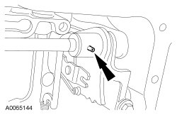
- Remove the manual control lever shaft.
- Remove the O-ring seals from the manual control lever shaft.
- Remove the manual control lever detent assembly.
- NOTICE: The intermediate/O/D band servo cover plate is spring loaded.
The bolts should be removed evenly until plate is unloaded, then remove the
bolts. Failure to do so can result in bolt thread damage.
Remove the 3 intermediate/O/D piston servo cover bolts and the servo cover.
- Remove the O-ring seal.
- Remove the intermediate/O/D servo piston.
- Remove the intermediate/O/D servo piston return spring.
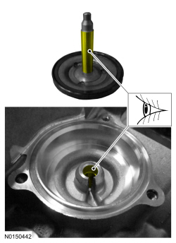
- NOTICE: If the intermediate/O/D servo bore has excessive wear, a lack
of apply pressure will occur and damage to the direct clutch and or intermediate/O/D
band may occur.
Inspect the intermediate/O/D servo bore and servo pin. If the intermediate/O/D servo bore or servo pin shows signs of excessive wear or damage, install a servo bore bushing. Refer to Servo Bore Repair.
- Rotate the transaxle 180 degrees.
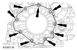
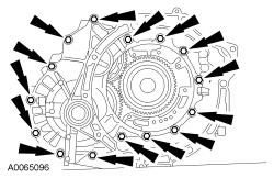
- Remove the bolts and separate the converter housing from the transaxle case.
- Remove the differential assembly.
- Remove the parking pawl assembly cover.
- Remove the bolts and the parking pawl assembly cover.
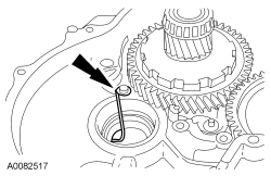
- Remove the parking pawl abutment.
- Unclip the spring.
- Remove the pin.
- Remove the lever.
- Remove the parking pawl abutment.
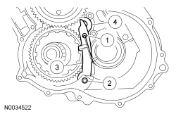
- Remove the spring.
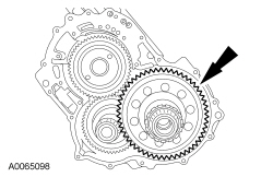
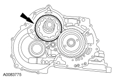
- Remove the transfer shaft gears.
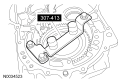
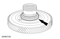
- Using the Final Drive Input Gear Holding Tool, lock the final drive input gear.
- Rotate the transaxle 180 degrees.
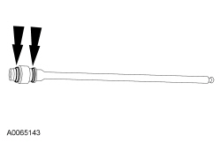
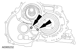
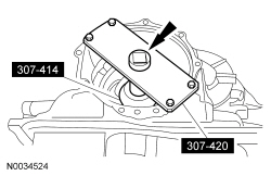
- NOTE:
Release the locking sleeve away from the final drive input gear bearing retainer nut.
Using the Final Drive Input Nut Socket and Wrench Guide Plate, remove the final drive input gear bearing retainer nut.
- Remove the Final Drive Input Nut Socket and Wrench Guide Plate.
- Rotate the transaxle 180 degrees.
- Remove the Final Drive Input Gear Holding Tool.
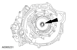
- NOTICE: Hold the final drive input gear while removing the bearing to
prevent it from falling out of the transaxle case or damage to the input gear
can occur.
Rotate the transaxle 180 degrees.
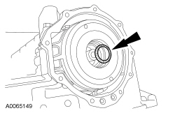
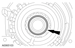
- Remove the final drive input gear bearing by lightly tapping on the end of the gear.
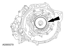
- Remove and discard the collapsible spacer.
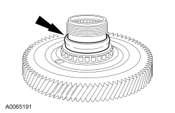
 WARNING: Wear
eye protection when servicing a vehicle. Failure to follow this instruction may result in serious personal injury.Using a chisel, remove the final drive input gear bearing.
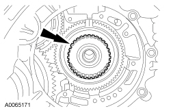
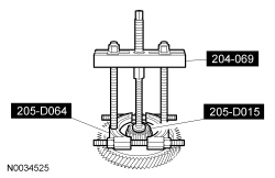
- Using the Front Wheel Hub Remover/Installer, Bearing Puller and Step Plate remove the final drive input gear bearing inner race.
- Clean the converter housing and transaxle case surfaces thoroughly with metal surface prep.
 Output Shaft Speed (OSS) Sensor
Material
Item
Specification
Motorcraft® MERCON® LV Automatic Transmission Fluid
XT-10-QLVC (US); CXT-10-LV12 (Canada)
MERCON® LV
Output Shaft Speed (OSS) Sen ...
 Transaxle - Disassembly (Manual Transaxle/Transmission — MTX75)
Special Tool(s)
Heat Gun
107-R0300 or equivalent
Holding Fixture, Transmission
307-003 (T57L-500-B)
Remover, Pilot Bearing
3 ...
More about Ford Focus:
Ford Focus Halfshaft - LH - Removal and Installation
Special Tool(s)
Installer, Halfshaft
204-161 (T97P-1175-A)
Remover, Front Wheel Hub
205-D070 (D93P-1175-B) or equivalent
Remover, Halfshaft
205-241 (T86P-3514-A)
Remover, Halfshaft (Plate)
205-290 (T ...
Nissan Frontier - Instrument Panel - Keys - Brake system
