Ford Focus Service Manual: Transaxle - Removal (Manual Transaxle/Transmission — MTX75)

|
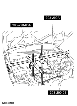
Adapter for 303-290A 303-290-01 |

|
Adapter for 303-290A (Support Leg) 303-290-03A |

|
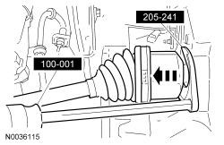
Remover, Halfshaft 205-241 (T86P-3514-A) |

|
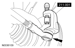
Remover, Tie-Rod End 211-001 (T00L-3290-D) |

|
Slide Hammer 100-001 (T50T-100-A) |

|
Support Bar, Engine 303-290A |
 WARNING: Do not
breathe dust or use compressed air to blow dust from storage containers or friction
components. Remove dust using government-approved techniques. Friction component
dust may be a cancer and lung disease hazard. Exposure to potentially hazardous
components may occur if dusts are created during repair of friction components,
such as brake pads and clutch discs. Exposure may also cause irritation to skin,
eyes and respiratory tract, and may cause allergic reactions and/or may lead to
other chronic health effects. If irritation persists, seek medical attention or
advice. Failure to follow these instructions may result in serious personal injury.
- With the vehicle in NEUTRAL, position it on a hoist. For additional information, refer to Section 100-02.
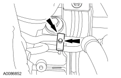
- Remove the steering column shaft bolt.
- Remove the battery. For additional information, refer to Section 414-01.
- Release the 2 wiring harness pushpins, then remove the 3 battery tray nuts and the battery tray.
- Remove the intake air hose.
- Disconnect the crankcase ventilation hose.
- Disconnect the booster bleed hose.
- Loosen the clamps and remove the intake air hose.
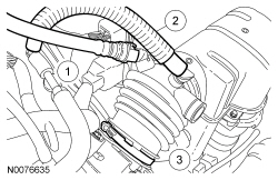
- Remove the 2 resonator bolts and the resonator.
- Disconnect the PCM electrical connectors.
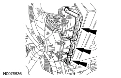
- Remove the PCM bolt and nut and the PCM.
- Remove the 3 PCM/battery support bracket bolts.
- Install the Engine Support Bar and Adapters.
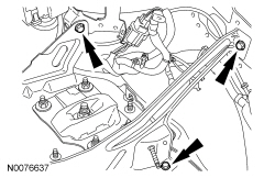
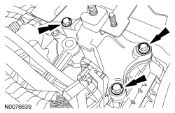
- Remove the 5 LH transaxle support insulator nuts and the LH transaxle support insulator with the PCM/battery support bracket.
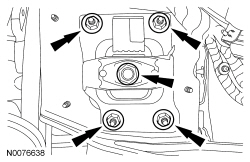
- Remove the 3 LH transaxle support insulator bracket bolts and the LH transaxle support insulator bracket.
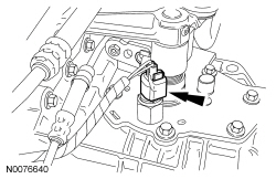
- Disconnect the reverse lamp switch electrical connector.
- Pressing the locking button, disconnect the gearshift cables from the transaxle.
- Disconnect the shift cable from the shift mass.
- Disconnect the selector cable from the selector lever.
- Remove the gearshift cables from the bracket.
- Disconnect the shift cable from the retaining bracket by pulling the abutment sleeves rearward then lifting the cable upward.
- Disconnect the selector cable from the retaining bracket by pulling the abutment sleeve rearward, then lifting the cable upward.
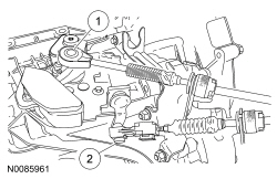
- Remove the bolt and the power steering tube clamp.
- Disconnect the clutch hydraulic tube and grommet from the retaining bracket.
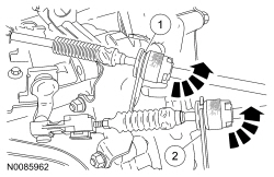
- Disconnect the Heated Oxygen Sensor (HO2S) and the catalyst monitor sensor electrical connectors. Remove the upper sensor bracket nut.
- Remove the 3 upper transmission-to-engine bolts.
- Remove the front wheels and tires. For additional information, refer to Section 204-04.
- If transaxle disassembly is necessary, drain the transaxle fluid.
- Remove the lower HO2S sensor bracket nut.
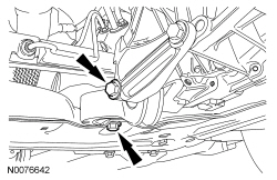
- Remove the 2 engine roll restrictor bolts and the engine roll restrictor.
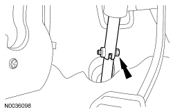
- Remove and discard the 2 tie-rod end nuts.
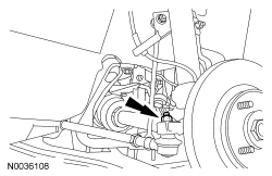
- Using the Tie-Rod End Remover, separate the tie-rod ends from the wheel knuckles.
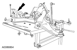
- Remove and discard the 2 lower control arm bolts and nuts and separate the lower control arms from the wheel knuckles.
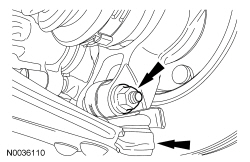
- Remove and discard the 2 stabilizer bar link nuts and separate the stabilizer bar links from the strut.
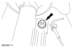
- Remove the power steering tube bolt, then disconnect the power steering tubes from the steering gear.
- NOTE:
Index-mark the subframe to the chassis.
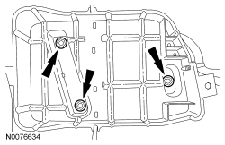
Position a suitable lifting device under the subframe. Remove the 6 subframe bolts.
- Lower the subframe assembly from the vehicle.
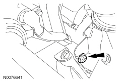
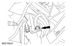
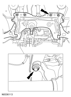
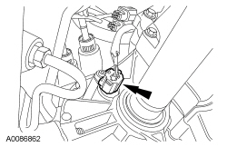
- Disconnect the Vehicle Speed Sensor (VSS) electrical connector.
- Remove the 2 locknuts and the intermediate shaft center bearing cap. Discard the locknuts and cap.
- NOTE:
Use a seal protector when removing the halfshaft. Splines on the halfshaft can damage the halfshaft seal. Do not let the halfshafts hang unsupported.
Remove the RH halfshaft from the transmission. Position it aside and secure it with mechanic's wire.
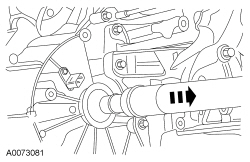
- NOTE:
Use a seal protector when removing the halfshaft. Splines on the halfshaft can damage the halfshaft seal. Do not let the halfshafts hang unsupported.
Using the Halfshaft Remover with the Slide Hammer, remove the LH halfshaft from the transmission. Position it aside and secure it with mechanic's wire.
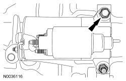
- Loosen the starter bolts, but do not remove the starter.
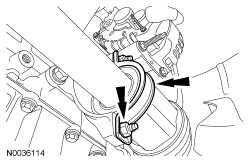
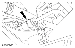
- Remove the clip, then disconnect the clutch hydraulic tube.
- Remove the exhaust flexible pipe. For additional information, refer to Section 309-00.
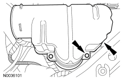
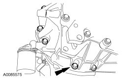
- Position a suitable jack to the transmission. Secure the transmission to the jack. Remove the 10 transaxle-to-engine bolts. Pull the transaxle rearward until the input shaft is clear of the pressure plate, then lower the transaxle from the vehicle.
 Transaxle - Installation (Manual Transaxle/Transmission — MTX75)
Material
Item
Specification
Motorcraft® Full Synthetic Manual Transmission Fluid
XT-M5-QS
WSD-M2C200-C
High Performance DOT 3 Motor Vehicle Brake Fluid
PM ...
 Transaxle - Removal (Automatic Transaxle/Transmission — 4F27E)
Special Tool(s)
Adapter for 303-290A
303-290-01
Adapter for 303-290A (Support Leg)
303-290-03A
Retainer, Torque Converter
3 ...
More about Ford Focus:
Ford Focus Output Shaft Speed (OSS) Sensor
Material
Item
Specification
Motorcraft® MERCON® LV Automatic Transmission Fluid
XT-10-QLVC (US); CXT-10-LV12 (Canada)
MERCON® LV
Output Shaft Speed (OSS) Sensor
Item
Part Number
Description
1
W500214-S439
Bolt
...
Nissan Frontier - Instrument Panel - Keys - Brake system
