Ford Focus Service Manual: Cylinder Head - Engine - 2.0L - in Vehicle Repair

|
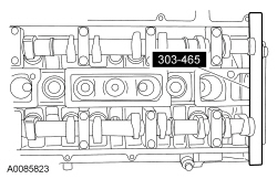
Alignment Plate, Camshaft 303-465 (T94P-6256-CH) |

|
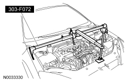
Engine Support Bar 303-F072 |
| Item | Specification |
|---|---|
| Motorcraft® Metal Surface Prep ZC-31-A | — |
| Motorcraft® SAE 5W-20 Premium Synthetic Blend Motor Oil (US); Motorcraft® SAE 5W-20 Super Premium Motor Oil (Canada) XO-5W20-QSP (US); CXO-5W20-LSP12 (Canada) | WSS-M2C945-A |
| Motorcraft® Silicone Gasket and Sealant TA-30 | WSE-M4G323-A4 |
| Motorcraft® Silicone Gasket Remover ZC-30 | — |
Cylinder Head (View 1 of 2)
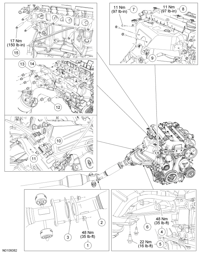
| Item | Part Number | Description |
|---|---|---|
| 1 | W705443 | Flexpipe-to-muffler and tailpipe assembly nut (2 required) |
| 2 | 5G232 | Flexpipe |
| 3 | 9451 | Flexpipe-to-muffler and tailpipe assembly gasket |
| 4 | W710512 | Catalytic converter-to-engine support bracket bolt (2 required) |
| 5 | — | Catalytic converter support bracket bolt (part of 5K222) (2 required) |
| 6 | 5K222 | Catalytic converter support bracket |
| 7 | — | Catalytic converter heat shield bolt (part of 5K282) (4 required) |
| 8 | W503922 | Catalytic converter heat shield bolt (2 required) |
| 9 | 5K282 | Catalytic converter heat shield |
| 10 | 14A624 | Heated Oxygen Sensor (HO2S) electrical connector (part of 12A690) |
| 11 | 14A624 | Catalyst Monitor Sensor (CMS) electrical connector (part of 12A690) |
| 12 | W703933 | Catalytic converter nut (7 required) |
| 13 | 5G232 | Catalytic converter |
| 14 | 9448 | Catalytic converter gasket |
| 15 | W704474 | Catalytic converter-to-cylinder head stud (7 required) |
Cylinder Head (View 2 of 2)
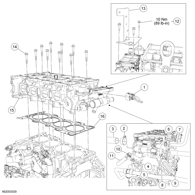
| Item | Part Number | Description |
|---|---|---|
| 1 | 14A464 | EGR valve electrical connector (part of 12B637) |
| 2 | 8287 | Upper radiator hose clamp |
| 3 | 8260 | Upper radiator hose |
| 4 | W52592 | EGR coolant tube clamp |
| 5 | 18K580 | EGR coolant hose (part of heater hose) |
| 6 | — | Engine coolant vent hose clamp (part of 8W005) |
| 7 | 8W005 | Engine coolant vent hose |
| 8 | — | Heater hose clamp (part of 18K580) |
| 9 | 18K580 | Heater hose |
| 10 | W525958 | Bypass hose clamp |
| 11 | 8548 | Bypass hose |
| 12 | W500204 | Wiring harness bracket bolt (2 required) |
| 13 | 14A301 | Wiring harness bracket |
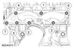
| 14 | 6065 | Cylinder head bolt (10 required) |
| 15 | 6050 | Cylinder head |
| 16 | 6051 | Cylinder head gasket |
Removal
NOTICE: Do not loosen or remove the crankshaft pulley bolt without first installing the special tools as instructed in this procedure. The crankshaft pulley and the crankshaft timing sprocket are not keyed to the crankshaft. The crankshaft, the crankshaft sprocket and the pulley are fitted together by friction, using diamond washers between the flange faces on each part. For that reason, the crankshaft sprocket is also unfastened if the pulley bolt is loosened. Before any repair requiring loosening or removal of the crankshaft pulley bolt, the crankshaft and camshafts must be locked in place by the special service tools, otherwise severe engine damage can occur.
NOTICE: During engine repair procedures, cleanliness is extremely important. Any foreign material, including any material created while cleaning gasket surfaces, that enters the oil passages, coolant passages or the oil pan can cause engine failure.
- Release the fuel system pressure. For additional information, refer to Section 310-00.
- Depower the Supplemental Restraint System (SRS) . For additional information, refer to Section 501-20B.
- Remove the battery tray. For additional information, refer to Section 414-01.
- Drain the cooling system. For additional information, refer to Section 303-03.
- Check the valve clearance. For additional information, refer to Valve Clearance Check in this section.
- Remove the generator. For additional information, refer to Section 414-00.
- Remove the 2 nuts and disconnect the flex pipe from the muffler and tailpipe
assembly.
- Remove and discard the nuts and gasket.
- Remove the 2 bolts from the catalytic converter-to-engine support bracket.
- Remove the 2 bolts and the catalytic converter support bracket.
- NOTE:
Mark the location of bolts for installation.
Remove the 6 bolts and the catalytic converter heat shield.
- Disconnect the Heated Oxygen Sensor (HO2S) and Catalyst Monitor Sensor (CMS) electrical connectors.
- Remove and discard the catalytic converter nuts.
- Position aside the catalytic converter and support with mechanic's wire.
- Remove and discard the catalytic converter gasket.
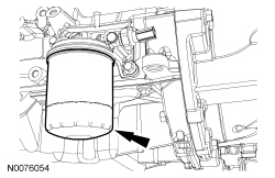
- Remove the engine oil filter and discard.
- Remove the fuel rail. For additional information, refer to Section 303-04.
- Remove the intake manifold. For additional information, refer to Intake Manifold in this section.
- Remove the timing drive components. For additional information, refer to Timing Drive Components in this section.
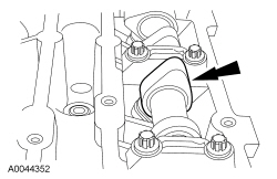
- Remove the Camshaft Alignment Plate.
- Mark the position of the camshaft lobes on the No. 1 cylinder for installation reference.
- NOTICE: Failure to follow the camshaft loosening procedure may result
in damage to the camshafts.
NOTE:
Mark the location and orientation of each camshaft bearing cap.
Remove the camshafts from the engine.- Loosen the camshaft bearing cap bolts, in sequence, one turn at a time.
- Repeat the first step until all tension is released from the camshaft bearing caps.
- Remove the camshaft bearing caps.
- Remove the camshafts.
- NOTE:
If the camshafts and valve tappets are to be reused, mark the location of the valve tappets to make sure they are assembled in their original positions.
Remove the valve tappets.
- NOTE:
The number on the valve tappets only reflects the digits that follow the decimal. For example, a tappet with the number 0.650 has the thickness of 3.650 mm.
Inspect the valve tappets. For additional information, refer to Section 303-00.
- Remove the 3 bolts and position the wiring harness and bracket aside.
- Disconnect the EGR valve electrical connector.
- Disconnect the coolant hoses from the coolant bypass.
- Disconnect the EGR coolant hose.
- Remove the 7 catalytic converter-to-cylinder head studs and discard.
- Lower the engine and remove the Engine Support Bar.
- Remove the 10 bolts and the cylinder head.
- Discard the bolts.
- Remove and discard the head gasket.
Installation
- NOTICE: Do not use metal scrapers, wire brushes, power abrasive discs
or other abrasive means to clean the sealing surfaces. These tools cause scratches
and gouges that make leak paths. Use a plastic scraping tool to remove all traces
of the head gasket.
NOTE:
Observe all warnings or cautions and follow all application directions contained on the packaging of the silicone gasket remover and the metal surface prep.
NOTE:
If there is no residual gasket material present, metal surface prep can be used to clean and prepare the surfaces.
Clean the cylinder head-to-cylinder block mating surface of both the cylinder head and the cylinder block in the following sequence.- Remove any large deposits of silicone or gasket material with a plastic scraper.
- Apply silicone gasket remover, following package directions, and allow to set for several minutes.
- Remove the silicone gasket remover with a plastic scraper. A second application of silicone gasket remover may be required if residual traces of silicone or gasket material remain.
- Apply metal surface prep, following package directions, to remove any traces of oil or coolant, and to prepare the surfaces to bond with the new gasket. Do not attempt to make the metal shiny. Some staining of the metal surfaces is normal.
- Clean the cylinder head bolt holes in the cylinder block. Make sure all coolant, oil or other foreign material is removed.
- Support the cylinder head on a bench with the head gasket side up. Check the cylinder head distortion and the cylinder block distortion. For additional information, refer to Section 303-00.
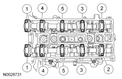
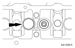
- Apply silicone gasket and sealant to the locations shown.
- Install a new cylinder head gasket.
- NOTE:
The cylinder head bolts are torque-to-yield and must not be reused. New cylinder head bolts must be installed.
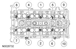
Install the cylinder head and the 10 new bolts. Tighten the bolts in the sequence shown in 5 stages.
- Stage 1: Tighten to 5 Nm (44 lb-in).
- Stage 2: Tighten to 15 Nm (133 lb-in).
- Stage 3: Tighten to 45 Nm (33 lb-ft).
- Stage 4: Turn 90 degrees.
- Stage 5: Turn an additional 90 degrees.
- Install the Engine Support Bar and raise the engine.
- Install the 7 new catalytic converter-to-cylinder head studs.
- Tighten to 17 Nm (150 lb-in).
- Install the EGR coolant hose.
- Connect the coolant hoses onto the coolant bypass.
- Connect the EGR valve electrical connector.
- Position the wire harness bracket and install the 3 bolts.
- Tighten to 10 Nm (89 lb-in).
- NOTE:
Lubricate the valve tappets with clean engine oil.
Install the valve tappets in their original positions.
- NOTICE: Install the camshafts with the alignment notches in the camshafts
lined up so the camshaft alignment plate can be installed. Make sure the lobes
on the No. 1 cylinder are in the same position at noted in the removal procedure.
Failure to follow this procedure can cause severe damage to the valves and pistons.
NOTE:
Lubricate the camshaft journals and bearing caps with clean engine oil.
Install the camshafts and bearing caps in their original location and orientation. Tighten the bearing caps in the sequence shown in 3 stages:- Stage 1: Tighten the camshaft bearing cap bolts, one turn at a time, until the cam is fully seated.
- Stage 2: Tighten to 7 Nm (62 lb-in).
- Stage 3: Tighten to 16 Nm (142 lb-in).
- Install the timing drive components. For additional information, refer to Timing Drive Components in this section.
- Install the intake manifold. For additional information, refer to Intake Manifold in this section.
- Install the fuel rail. For additional information, refer to Section 303-04.
- Clean and inspect the catalytic converter flange. For additional information, refer to exhaust manifold cleaning and inspection in Section 303-00.
- NOTICE: Failure to tighten the catalytic converter nuts to specification
before installing the converter bracket bolts will cause the converter to develop
an exhaust leak.
NOTICE: Failure to tighten the catalytic converter nuts to specification a second time will cause the converter to develop an exhaust leak.
Using a new gasket and 7 new nuts, install the catalytic converter and tighten in 2 stages in the sequence shown.- Stage 1: Tighten to 55 Nm (41 lb-ft).
- Stage 2: Tighten to 55 Nm (41 lb-ft).
- Connect the HO2S and CMS electrical connectors.
- Install the catalytic converter heat shield and 6 bolts.
- Tighten to 11 Nm (97 lb-in).
- Install the catalytic converter support bracket and the 2 bolts.
- Tighten to 22 Nm (16 lb-ft).
- Install the 2 catalytic converter-to-engine support bracket bolts.
- Tighten to 48 Nm (35 lb-ft).
- NOTE:
Clean the mating surfaces of the muffler assembly and the flexpipe.
Using a new gasket and 2 new nuts, connect the muffler and tailpipe assembly to the flexpipe.
- Tighten to 48 Nm (35 lb-ft).
- Install the generator. For additional information, refer to Section 414-00.
- Install the battery tray. For additional information, refer to Section 414-01.
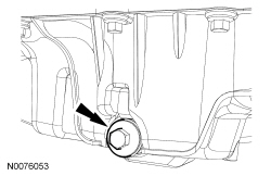
- Drain the engine oil.
- Install the drain plug and tighten to 28 Nm (21 lb-ft).
- NOTE:
Lubricate the engine oil filter gasket with clean engine oil prior to installing the oil filter.
Install a new engine oil filter.
- Tighten the oil filter three-fourths turn after the oil filter gasket makes contact with the oil filter adapter.
- Fill the engine with clean engine oil.
- Fill and bleed the cooling system. For additional information, refer to Section 303-03.
- Repower the SRS . For additional information, refer to Section 501-20B.
 Cylinder Head - Engine - 2.0L - Disassembly and Assembly of Subassemblies
Special Tool(s)
Compressor, Valve Spring
303-300 (T87C-6565-A)
Compressor, Valve Spring
303-350 (T89P-6565-A)
Compressor, Valve ...
 Cylinder Head Distortion
Special Tool(s)
Feeler Gauge Set
303-D027 (D81L-4201-A) or equivalent
NOTE: Refer to the appropriate Section 303-01 for the specification.
NOTE: Make sure all cy ...
More about Ford Focus:
Ford Focus Outer Constant Velocity (CV) Joint Boot
Special Tool(s)
Installer, Constant Velocity Joint Boot Clamp
205-343 (T95P-3514-A)
Material
Item
Specification
Constant Velocity Joint Grease (High Temperature)
XG-5
WSS-M1C258-A1
Removal
Remove the inner CV joint boot. F ...
Nissan Frontier - Instrument Panel - Keys - Brake system
