Ford Focus Service Manual: Engine Front Cover

|
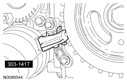
Aligner, Crankshaft Sensor 303-1417 |

|
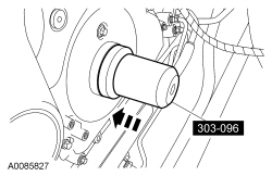
Installer, Camshaft Front Oil Seal 303-096 (T74P-6150-A) |

|
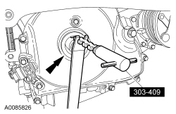
Remover, Oil Seal 303-409 (T92C-6700-CH) |
| 6 mm x 18 mm bolt |
| Item | Specification |
|---|---|
| Motorcraft® SAE 5W-20 Premium Synthetic Blend Motor Oil (US); Motorcraft® SAE 5W-20 Super Premium Motor Oil (Canada) XO-5W20-QSP (US); CXO-5W20-LSP12 (Canada) | WSS-M2C945-A |
| Motorcraft® Silicone Gasket and Sealant TA-30 | WSE-M4G323-A4 |
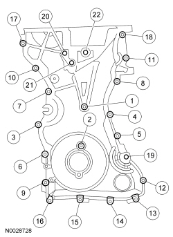
| Item | Part Number | Description |
|---|---|---|
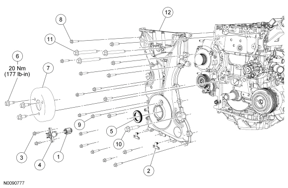
| 1 | 14A464 | Crankshaft Position (CKP) sensor electrical connector (part of 12A690) |
| 2 | 13A506 | Wiring harness retainer (part of 12A690) (2 required) |
| 3 | W701219 | CKP sensor bolt (2 required) |
| 4 | 6C315 | CKP sensor |
| 5 | 6700 | Crankshaft front seal |
| 6 | W500221 | Coolant pump pulley bolt (3 required) |
| 7 | 8509 | Coolant pump pulley |
| 8 | W500215 | Engine front cover bolt (17 required) |
| 9 | W500300 | Engine front cover bolt |
| 10 | W500320 | Engine front cover bolt |
| 11 | W500328 | Engine front cover bolt (3 required) |
| 12 | 6019 | Engine front cover |
Removal
NOTICE: Do not loosen or remove the crankshaft pulley bolt without first installing the special tools as instructed in this procedure. The crankshaft pulley and the crankshaft timing sprocket are not keyed to the crankshaft. The crankshaft, the crankshaft sprocket and the pulley are fitted together by friction, using diamond washers between the flange faces on each part. For that reason, the crankshaft sprocket is also unfastened if the pulley bolt is loosened. Before any repair requiring loosening or removal of the crankshaft pulley bolt, the crankshaft and camshafts must be locked in place by the special service tools, otherwise severe engine damage can occur.
NOTICE: During engine repair procedures, cleanliness is extremely important. Any foreign material, including any material created while cleaning gasket surfaces, that enters the oil passages, coolant passages or the oil pan can cause engine failure.
- With the vehicle in NEUTRAL, position it on a hoist. For additional information, refer to Section 100-02.
- Depower the Supplemental Restraint System (SRS) . For additional information, refer to Section 501-20B.
- Loosen the 3 coolant pump pulley bolts.
- Remove the crankshaft pulley. For additional information, refer to Crankshaft Pulley in this section.
- Disconnect the Crankshaft Position (CKP) sensor electrical connector.
- Detach the 2 wiring harness retainers from the engine front cover.
- Remove the 2 bolts and the CKP sensor.
- NOTICE: Use care not to damage the engine front cover or the crankshaft
when removing the seal.
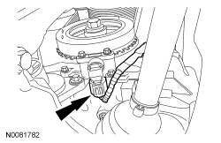
Using the Oil Seal Remover, remove the crankshaft front oil seal.
- Remove the 3 bolts and the coolant pump pulley.
- Remove the coolant expansion tank. For additional information, refer to Section 303-03.
- Remove the power steering pump. For additional information, refer to Section 211-02.
- Remove the engine mount. For additional information, refer to Engine Mount in this section.
- Slightly raise the engine for access to the accessory drive idler pulley.
- Remove the accessory drive idler pulley. For additional information, refer to Section 303-05.
- Remove the bolts and the engine front cover.
Installation
- NOTICE: Do not use metal scrapers, wire brushes, power abrasive disks
or other abrasive means to clean sealing surfaces. These tools cause scratches
and gouges which make leak paths.
Clean and inspect the mounting surfaces of the engine and the front cover.
- NOTE:
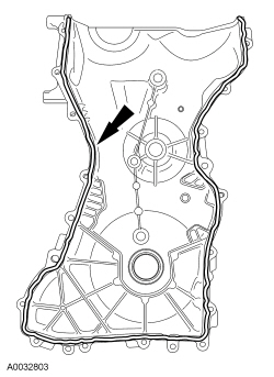
The engine front cover must be installed and the bolts tightened within 4 minutes of applying the silicone gasket and sealant.
Apply a 2.5 mm (0.10 in) bead of silicone gasket and sealant to the cylinder head and oil pan joint areas. Apply a 2.5 mm (0.10 in) bead of silicone gasket and sealant to the front cover.
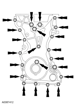
- Install the engine front cover. Tighten the bolts in the sequence shown,
to the following specifications:
- Tighten the 8-mm bolts to 10 Nm (89 lb-in).
- Tighten the 13-mm bolts to 48 Nm (35 lb-ft).
- Install the accessory drive idler pulley. For additional information, refer to Section 303-05.
- Lower the engine to the installed position.
- Install the engine mount. For additional information, refer to Engine Mount in this section.
- Install the power steering pump. For additional information, refer to Section 211-02.
- Install the coolant expansion tank. For additional information, refer to Section 303-03.
- Install the coolant pump pulley and the 3 bolts.
- Do not tighten at this time.
- NOTE:
Remove the through-bolt from the Camshaft Front Oil Seal Installer.
NOTE:
Lubricate the oil seal with clean engine oil.
Using the Camshaft Front Oil Seal Installer, install the crankshaft front oil seal.
- Install the crankshaft pulley. For additional information, refer to Crankshaft Pulley in this section.
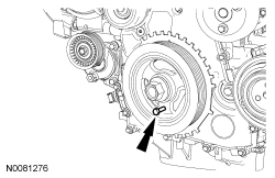
- NOTICE: Only hand-tighten the bolt or damage to the front cover can occur.
Install a standard 6 mm x 18 mm bolt through the crankshaft pulley and thread it into the front cover.
- Install the CKP sensor and the 2 bolts.
- Do not tighten the bolts at this time.
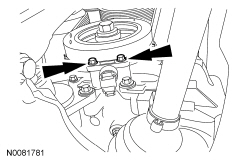
- Using the Crankshaft Sensor Aligner, adjust the CKP sensor.
- Tighten the 2 bolts to 7 Nm (62 lb-in).
- Connect the CKP sensor electrical connector.
- Attach the 2 wiring harness retainers to the engine front cover.
- Remove the 6 mm x 18 mm bolt.
- Tighten the coolant pump pulley bolts.
- Tighten to 20 Nm (177 lb-in).
- Repower the SRS . For additional information, refer to Section 501-20B.
- Fill the power steering system. For additional information, refer to Section 211-00.
 Intermediate Shaft Bearing
Special Tool(s)
Puller, Bearing
205-D064 (D84L-1123-A)
Removal
Remove the intermediate shaft. For additional information, refer to Intermediate
Shaft in this s ...
 Crankshaft Main Bearing Journal Diameter
NOTE: Refer to the appropriate Section 303-01 for the specification.
Measure each of the crankshaft main bearing journal diameters in at least
2 directions.
...
More about Ford Focus:
Ford Focus Connecting Rod to Crankshaft Side Clearance
Special Tool(s)
Feeler Gauge Set
303-D027 (D81L-4201-A) or equivalent
NOTE: Refer to the appropriate Section 303-01 for the specification.
Using the Feeler Gauge Set, measure the clearance between the connecting
rod and the crankshaft. Verify the measurement ...
Nissan Frontier - Instrument Panel - Keys - Brake system
