Ford Focus Service Manual: Frame Members
| 3 Phase Inverter Spot Welder 254-00002 |
| Compuspot 700F Welder 190-50080 |
| I4 Inverter Spot Welder 254-00014 |
| Inverter Welder with MIG Welder 254-00015 |
| Item | Specification |
|---|---|
| Motorcraft® Metal Surface Prep ZC-31-A | — |
Front Frame Rails — Exploded View
 WARNING: Frame
rail crush zones absorb crash energy during a collision and must be replaced if
damaged. Prior to replacement of frame rail crush zones, straighten damaged frame
rails to correct frame dimensions. Failure to follow these instructions may adversely
affect frame rail crush zone performance and may result in serious personal injury
to vehicle occupants in a crash.
WARNING: Invisible
ultraviolet and infrared rays emitted in welding can injure unprotected eyes and
skin. Always use protection such as a welder's helmet with dark-colored filter lenses
of the correct density. Electric welding will produce intense radiation, therefore,
filter plate lenses of the deepest shade providing adequate visibility are recommended.
It is strongly recommended that persons working in the weld area wear flash safety
goggles. Also wear protective clothing. Failure to follow these instructions may
result in serious personal injury.
NOTE:
Left side shown, right side similar.
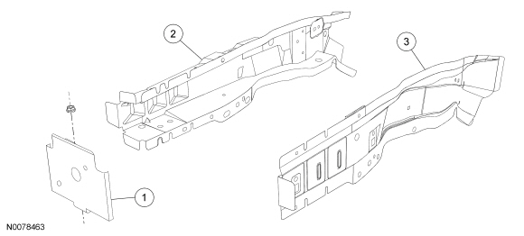
| Item | Part Number | Description |
|---|---|---|
| 1 | 108K34 | Reinforcement — High-Strength Low Alloy (HSLA) 350 steel |
| 2 | 16055-AB LH/ 16054-TA RH | Apron assembly front fender lower inner — HSLA 350 steel |
| 3 | 16055-AC LH/ 16054-RA RH | Apron assembly front fender lower outer — HSLA 350 steel |
WARNING: Collision
damage repair must conform to the instructions contained in this workshop manual.
Replacement components must be new, genuine Ford Motor Company parts. Recycled,
salvaged, aftermarket or reconditioned parts (including body parts, wheels or safety
restraint components) are not authorized by Ford.
- WARNING: Frame
rail crush zones absorb crash energy during a collision and must be replaced if damaged. Prior to replacement of frame rail crush zones, straighten damaged frame rails to correct frame dimensions. Failure to follow these instructions may adversely affect frame rail crush zone performance and may result in serious personal injury to vehicle occupants in a crash.Position the vehicle on a frame repair rack following the manufacturer's recommendations. Measure the vehicle to determine if the body requires rough straightening and alignment. For dimensional information, refer to Body in this section.
- Remove the hood. For additional information, refer to Section 501-02.
- Remove the battery. For additional information, refer to Section 414-01.
- Remove the fender(s) from the affected side(s). For additional information, refer to Section 501-02.
- Remove the front bumper cover. For additional information, refer to Section 501-19.
- NOTE:
If the front bumper beam is not damaged and will be reinstalled, it is spot-welded to the frame rails and must be removed.
Remove the front bumper beam.
- Remove the upper radiator grille opening panel reinforcement. For additional information, refer to Section 501-02.
- Discharge the A/C system. For additional information, refer to Section 412-00.
- Remove the condenser core. For additional information, refer to Section 412-00.
- Remove the lower radiator support.
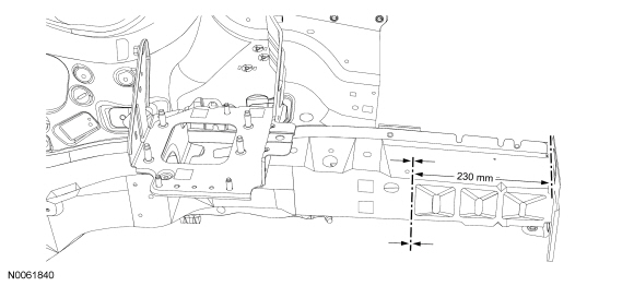
- Scribe a cut-line 230 mm (9.05 in) from the front bumper bracket on the inner frame rail. Using a reciprocating saw, plasma cutter or cut-off wheel, cut completely through the inner and outer frame rails and remove.
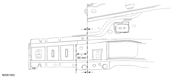
- Scribe a cut-line 60 mm (2.36 in) rearward of the initial frame rail cut, on the outer portion of the rail assembly. Using a cut-off wheel or equivalent, cut and remove that portion of outer rail only. This will create an overlap joint.
- Measure and cut the inner and outer service replacement rails, equivalent to the length of the damaged frame rail section.
- Remove the E-coat from the existing frame rails and service replacement
rails, including around the holes to be welded, by grinding or sanding until
bare metal is visible.
- Wire brush any foreign material from the edges within 15 mm (0.59 in) of the repair joint.
- Install and clamp the service replacement inner frame rail in place. Tack weld and verify correct alignment of the frame rail.
- Seam weld along the inside of the section joint using a Metal Inert Gas
(MIG) welder and ER70S-3 wire 0.9 mm (0.035 in) to 0.11 mm (0.045 in) diameter
wire.
- Verify correct alignment and underbody dimensions.
- Use a dye penetrant or equivalent to determine if any cracks or large voids exist, grind out any defects that exist and repair until the weld is free of defects.
- Dress welds as necessary and restore corrosion protection to bare metal surfaces.
- Install and clamp the service replacement outer frame rail in place.
- Verify correct alignment of the outer frame rail.
- Seam weld along the section joint of the outer frame rail using a MIG and ER70S-3 wire 0.9 mm (0.035 in) to 0.11 mm (0.045 in) diameter wire.
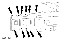
- NOTE:
Factory spot welds may be substituted with either resistance spot welds or MIG plug welds. Spot/plug welds should equal factory welds in both location and quantity. Do not place a new spot weld directly over an original weld location. Plug weld hole should equal 8 mm (0.31 in) diameter.
Using a MIG welder or resistance spot welder, plug weld along the top and bottom seam of the service replacement rails.
- Use a dye penetrant or equivalent to determine if any cracks or large voids
exist, grind out any defects that exist and repair until the weld is free of
defects.
- Dress welds as necessary and restore corrosion protection to bare metal surfaces.
- Reinstall the components removed during disassembly.
 Restoring Corrosion Protection Following Repair
Special Tool(s)
Rust Inhibitor Installation Kit
286-00002
Undercoating Spray Gun
286-00001
Material
Item
Specification
...
 Roof Pillars
...
More about Ford Focus:
Ford Focus Transaxle Rear Support Insulator
Item
Part Number
Description
1
W702826-S
Roll restrictor-to-subframe bolt
2
W702801-S
Roll restrictor-to-transaxle bracket bolt
3
6P082
Roll restrictor
Removal and Installation
With the vehicle in NEUTRAL, posit ...
Nissan Frontier - Instrument Panel - Keys - Brake system
