Ford Focus Service Manual: Front Suspension Stabilizer Bar

|
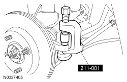
Remover, Tie-Rod End 211-001 (TOOL-3290-D) |
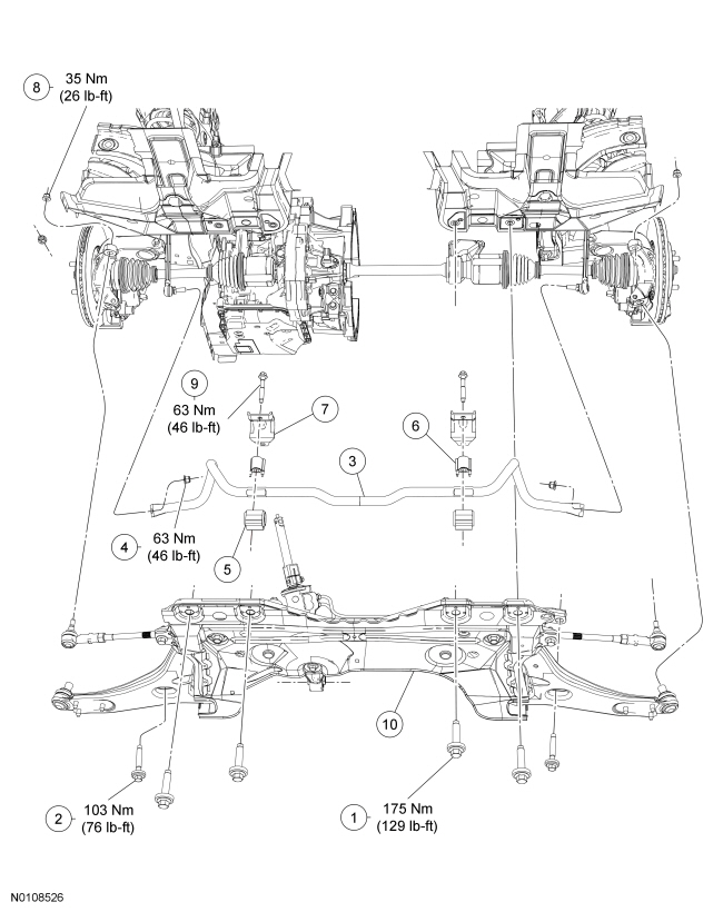
| Item | Part Number | Description |
|---|---|---|
| 1 | W710091 | Subframe front bolt (4 required) |
| 2 | W709634 | Subframe rear bolt (2 required) |
| 3 | 5494 | Stabilizer bar |
| 4 | W715135 | Stabilizer bar link lower nut (2 required) |
| 5 | 5484 | Stabilizer bar bushing (2 required) |
| 6 | 51836 | Stabilizer bar spacer (2 required) |
| 7 | 5488 | Stabilizer bar bushing bracket (2 required) |
| 8 | W520203 | Tie-rod end nut (2 required) |
| 9 | W710899/900 | Stabilizer bar bracket bolt (4 required) |
| 10 | 5019 | Subframe |
Removal
NOTICE: Suspension fasteners are critical parts because they affect performance of vital components and systems and their failure may result in major service expense. New parts must be installed with the same part numbers or equivalent part, if replacement is necessary. Do not use a replacement part of lesser quality or substitute design. Torque values must be used as specified during reassembly to make sure correct retention of these parts.
NOTICE: Do not use power tools to remove or install the stabilizer bar link nuts or damage to the stabilizer bar link ball joints or boots may occur.
NOTICE: Do not hold the stabilizer bar link boot with any tool or damage to the boot may occur.
NOTICE: Use the internal or external hex-holding feature to prevent the ball and stud from turning while removing or installing the stabilizer bar link nuts. The link boot seal must not be allowed to twist while tightening the link nuts or damage to the boot seal will occur.
NOTE:
The stabilizer bar links are designed with low friction ball joints that have a low breakaway torque.
- Remove the wheel and tire. For additional information, refer to Section 204-04.
- Loosen the tie-rod end nuts.
- Using the Tie-Rod End Remover, detach the tie-rod ends from the wheel knuckles.
- Discard the tie-rod end nuts.
- Remove and discard the stabilizer bar link lower nuts and detach the stabilizer bar links from the stabilizer bar.
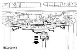
- Using a suitable transmission jack, support the subframe.
- Index-mark the subframe position.
- Remove the 4 subframe front bolts and 2 subframe rear bolts.
- NOTICE: The power steering lines are attached to the steering gear. Failure
to use caution when lowering the subframe may result in steering line damage.
Lower the subframe to gain access to the stabilizer bar.
- Remove the stabilizer bar bracket bolts and brackets.
- Discard the bolts.
- Remove the stabilizer bar bushings.
- Remove the stabilizer bar.
Installation
- Install the stabilizer bar.
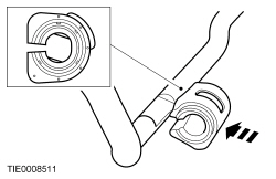
- NOTICE: The stabilizer bar bushings must be positioned correctly on the
flats of the stabilizer bar or damage to the bushings may occur.
NOTICE: Do not apply any type of lubricant to the stabilizer bar or bushings or damage to the bushings may occur.
Install the stabilizer bar bushings.
- Position the stabilizer bar with the bushings against the spacer and set it to the specification listed using tie straps or mechanic's wire.
- Position the stabilizer bar brackets and install the new bolts.
- Tighten to 63 Nm (46 lb-ft).
- Remove the stabilizer bar supports.
- NOTE:
Do not fully tighten the subframe bolts at this time.
Using the index marks made during removal, install the subframe bolts.
- Tighten the bolts until snug.
- NOTE:
While tightening the subframe bolts, make sure the subframe does not move.
Tighten the 4 subframe front bolts.
- Tighten to 175 Nm (129 lb-ft).
- NOTE:
While tightening the subframe bolts, make sure the subframe does not move.
Tighten the 2 subframe rear bolts.
- Tighten to 103 Nm (76 lb-ft).
- Lower and remove the transmission jack.
- Attach the stabilizer bar links to the stabilizer bar and install the new
nuts.
- Tighten to 63 Nm (46 lb-ft).
- NOTICE: Install new tie-rod end nuts. Failure to follow this instruction
may result in incorrect clamp load.
Attach the tie-rod ends to the wheel knuckles and install the new nuts.
- Tighten to 35 Nm (26 lb-ft).
- Install the wheel and tire. For additional information, refer to Section 204-04.

 Rear Suspension Stabilizer Bar
Item
Part Number
Description
1
W710903
Stabilizer bar bracket bolt (4 required)
2
5B484
Stabilizer bar bracket (2 required)
3
4A ...
More about Ford Focus:
Ford Focus Electronic Leak Detection
Special Tool(s)
Heated Pentode Halogen Leak Detector
023-00178 or equivalent
NOTE: Good ventilation is necessary in the area where electronic A/C
leak testing is to be carried out. If the surrounding air is contaminated with refrigerant
gas, the Heated Pentode Ha ...
Nissan Frontier - Instrument Panel - Keys - Brake system
