Ford Focus Service Manual: Front Suspension Wheel Knuckle

|
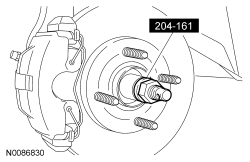
Installer, Halfshaft 204-161 (T97P-1175-A) |

|
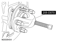
Remover, Front Wheel Hub 205-D070 (D93P-1175-B) or equivalent |

|
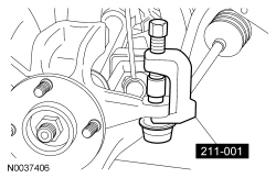
Remover, Tie-Rod End 211-001 (TOOL-3290-D) |
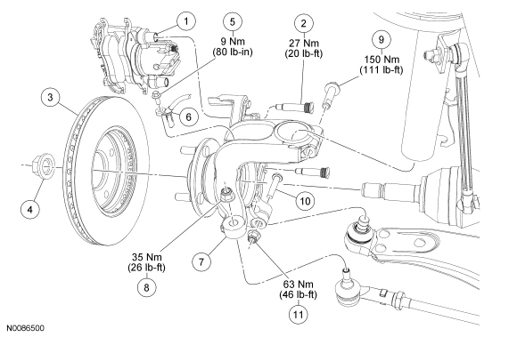
| Item | Part Number | Description |
|---|---|---|
| 1 | — | Brake caliper and pad assembly |
| 2 | — | Brake caliper guide pin bolt (2 required) (part of 2386 service kit) |
| 3 | 1125 | Brake disc |
| 4 | 3B477 | Wheel hub nut |
| 5 | W5000012 | Wheel speed sensor bolt |
| 6 | 2C204 | Wheel speed sensor |
| 7 | 3K171 LH/ 3K170 RH | Wheel knuckle and hub assembly |
| 8 | W520203 | Tie-rod end nut |
| 9 | W711725 | Wheel knuckle-to-strut bolt |
| 10 | W712393 | Ball joint bolt |
| 11 | W520213 | Ball joint nut |
Removal
NOTICE: Suspension fasteners are critical parts because they affect performance of vital components and systems and their failure may result in major service expense. New parts must be installed with the same part numbers or equivalent part, if replacement is necessary. Do not use a replacement part of lesser quality or substitute design. Torque values must be used as specified during reassembly to make sure correct retention of these parts.
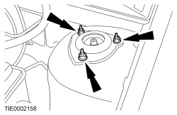
- Loosen the 3 strut upper nuts 5 turns.
- Remove the wheel and tire. For additional information, refer to Section 204-04.
- Remove and discard the wheel hub nut.
- Remove the brake hose retainer.
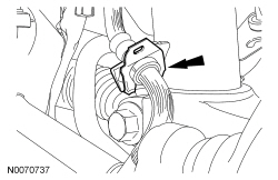
- NOTICE: Do not allow the brake caliper to hang from the brake hose or
damage to the hose can occur.
Remove the 2 brake caliper guide pin bolts and position the caliper assembly aside.
- Support the caliper assembly using mechanic's wire.
- Remove the brake disc.
- If equipped with ABS, remove the wheel speed sensor bolt and position the sensor aside.
- NOTICE: Leave the tie-rod end nut in place or damage to the tie-rod end
may occur.
Loosen the tie-rod end nut.
- Using the Tie-Rod End Remover, detach the tie-rod end from the wheel knuckle.
- Remove and discard the tie-rod end nut.
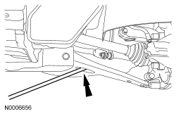
- NOTICE: Do not use a prying device or separator fork between the ball
joint and the wheel knuckle. Damage to the ball joint or ball joint seal may
result. Only use the pry bar by inserting it into the lower arm body opening.
NOTICE: Use care when releasing the lower arm and wheel knuckle into the resting position or damage to the ball joint seal may occur.
Remove and discard the ball joint nut and bolt.- Insert a pry bar in the lower arm body opening and separate the ball joint from the wheel knuckle.
- NOTICE: The inner joint must not be bent more than 18 degrees. The outer
joint must not be bent more than 45 degrees. Damage to the halfshaft will occur.
Using the Front Wheel Hub Remover, press out the halfshaft from the wheel hub and detach the halfshaft from the wheel hub.
- Support the halfshaft.
- Remove and discard the wheel knuckle-to-strut bolt.
- Remove the wheel knuckle.
Installation
- Position the wheel knuckle and install a new wheel knuckle-to-strut bolt.
- Tighten to 150 Nm (111 lb-ft).
- Insert the halfshaft into the wheel hub.
- NOTICE: Make sure the ball joint heat shield is installed on the ball
joint stud or damage to the ball joint may occur.
Insert the ball joint stud into the wheel knuckle and install a new bolt and nut.
- Tighten to 63 Nm (46 lb-ft).
- Attach the tie-rod end to the wheel knuckle and install a new nut.
- Tighten to 35 Nm (26 lb-ft).
- If equipped with ABS, position the wheel speed sensor and install the bolt.
- Tighten to 9 Nm (80 lb-in).
- Install the brake disc.
- Position the caliper assembly and install the 2 brake caliper guide pin
bolts.
- Tighten to 27 Nm (20 lb-ft).
- Install the brake hose retainer.
- Tighten the 3 strut upper nuts to 35 Nm (26 lb-ft).
- Using the Halfshaft Installer, install the halfshaft into the wheel hub.
- NOTICE: Do not tighten the wheel hub nut with the vehicle on the ground.
The nut must be tightened to specification before the vehicle is lowered onto
the wheels. Wheel bearing damage will occur if the wheel bearing is loaded with
the weight of the vehicle applied.
NOTICE: Install and tighten the new wheel hub nut to specification in a continuous rotation. Always install a new wheel hub nut after loosening or when not tightened to specification in a continuous rotation or damage to the component may occur.
NOTE:
Apply the brake to keep the halfshaft from rotating.
Install the new wheel hub nut.- Tighten to 270 Nm (199 lb-ft) in a continuous rotation.
- Install the wheel and tire. For additional information, refer to Section 204-04.
 Knuckles
...
 Rear Suspension Wheel Knuckle
Item
Part Number
Description
1
2210
Drum brake assembly
2
W500746
Rearward lower arm outboard bolt
3
5A969 LH/ 5A968 RH
Wheel ...
More about Ford Focus:
Ford Focus Towing points
Towing eye location
The screw-in towing eye is located in the
spare wheel well.
Insert your finger into the hole on the
underside of the cover and prise off the
cover. On vehicles with a body styling kit,
insert your fingers into the hole in the
bezel and pull off the complete bezel.
Ins ...
Nissan Frontier - Instrument Panel - Keys - Brake system
