Ford Focus Service Manual: Halfshaft - RH

|
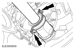
Installer, Halfshaft 204-161 (T97P-1175-A) |

|
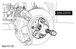
Remover, Front Wheel Hub 205-D070 (D93P-1175-B) or equivalent |
| Item | Specification |
|---|---|
| Motorcraft® Full Synthetic Manual Transmission Fluid XT-M5-QS | WSD-M2C200-C |
| Motorcraft® MERCON® LV Automatic Transmission Fluid XT-10-QLV | MERCON® LV |
NOTE:
Automatic shown, manual similar.
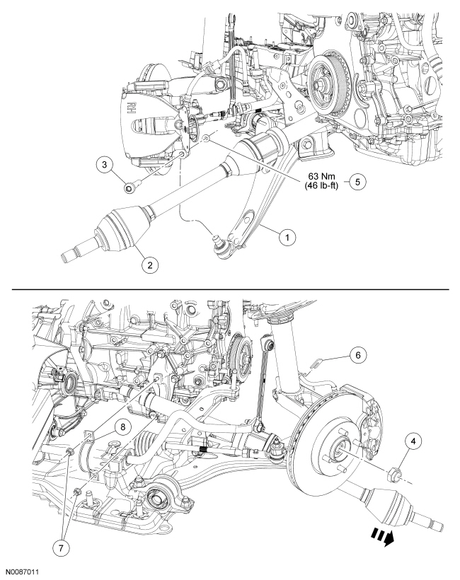
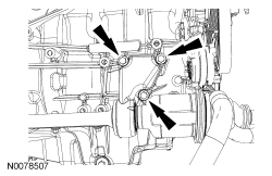
| Item | Part Number | Description |
|---|---|---|
| 1 | 3042 | Lower arm |
| 2 | — | Halfshaft assembly |
| 3 | W712393 | Ball joint bolt |
| 4 | 3B477 | Wheel hub nut |
| 5 | W520213 | Ball joint nut |
| 6 | — | Brake hose retainer |
| 7 | W520102-S | Intermediate shaft support bearing strap nuts (2 required) |
| 8 | 3N324 | Intermediate shaft support bearing strap |
Removal
All vehicles
- With the vehicle in NEUTRAL, position it on a hoist. For additional information, refer to Section 100-02.
- Remove the RH wheel and tire. For additional information, refer to Section 204-04.
- Remove and discard the wheel hub nut.
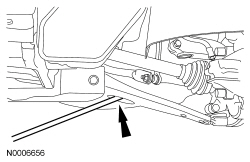
- NOTICE: Do not use a prying device or separator fork between the ball
joint and the wheel knuckle. Damage to the ball joint or ball joint seal may
result. Only use the pry bar by inserting it into the lower arm body opening.
NOTICE: Use care when releasing the lower arm and wheel knuckle into the resting position or damage to the ball joint seal may occur.
Remove and discard the ball joint nut and bolt.- Insert a pry bar in the lower arm body opening and separate the ball joint from the wheel knuckle.
- NOTICE: The inner joint must not be bent more than 18 degrees. The outer
joint must not be bent more than 45 degrees. Damage to the halfshaft will occur.
Using the Front Wheel Hub Remover, press out the halfshaft from the wheel hub and detach the RH halfshaft from the wheel hub.
- Support the halfshaft assembly.
- Remove the brake hose retainer.
Automatic transmission vehicles
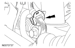
- Remove and discard the retaining strap and 2 nuts.
Manual transmission vehicles
- Remove and discard the 3 bracket-to-block bolts.
All vehicles
- Remove the RH halfshaft assembly.
Installation
All vehicles
- Install the RH halfshaft assembly into the transmission.
Automatic transmission vehicles
- NOTE:
Install a new retaining strap and 2 nuts on the intermediate shaft bearing.
Install the RH halfshaft assembly into the transmission.
- Tighten the lower nut to 5 Nm (44 lb-in).
- Tighten the upper nut to 25 Nm (18 lb-ft).
- Tighten the lower nut to 25 Nm (18 lb-ft).
Manual transmission vehicles
NOTE:
Insert the halfshaft assembly into the transmission until the intermediate shaft bearing contacts the rib of the intermediate shaft bracket.
- Install the halfshaft assembly into the transmission.
- Install the 3 new bracket bolts to the engine block.
- Tighten to 48 Nm (35 lb-ft).
All vehicles
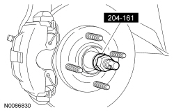
- Using the Halfshaft Installer, install the RH halfshaft into the wheel hub.
- NOTICE: Make sure the ball joint heat shield is installed on the ball
joint stud or damage to the ball joint may occur.
Insert the ball joint stud into the wheel knuckle and install a new bolt and nut.
- Tighten to 63 Nm (46 lb-ft).
- NOTICE: Do not tighten the wheel hub nut with the vehicle on the ground.
The nut must be tightened to specification before the vehicle is lowered onto
the wheels. Wheel bearing damage will occur if the wheel bearing is loaded with
the weight of the vehicle applied.
NOTICE: Install and tighten the new wheel hub nut to specification in a continuous rotation. Always install a new wheel hub nut after loosening or when not tightened to specification in a continuous rotation or damage to the components may occur.
NOTE:
Apply the brake to keep the halfshaft from rotating.
Install a new wheel hub nut.- Tighten to 270 Nm (199 lb-ft) in a continuous rotation.
- Install the brake hose retainer.
- Install the RH wheel and tire. For additional information, refer to Section 204-04.
- Top off the transmission fluid level.
 Halfshaft - RH - Disassembly and Assembly
Special Tool(s)
Installer, Constant Velocity Joint Boot Clamp
205-343 (T95P-3514-A)
Puller, Bearing
205-D064 (D84L-1123-A)
Material
...
 Inner Constant Velocity (CV) Joint Boot
Special Tool(s)
Installer, Constant Velocity Joint Boot Clamp
205-343 (T95P-3514-A)
Material
Item
Specification
Constant Velocity Joint Grease ...
More about Ford Focus:
Ford Focus Insulation
Body insulation is comprised of urethane, Polyvinyl Chloride (PVC) , foam
and recycled felt. Insulation is used as a sound deadener to reduce exterior road
and powertrain noises from the interior of the vehicle. Baffles are located in the
bottom of the A-, B- and C-pillars. Mastic insula ...
Nissan Frontier - Instrument Panel - Keys - Brake system
