
Ford Focus Service Manual: Intake Manifold
Intake Manifold (View 1 of 3)
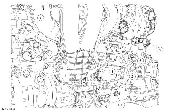
| Item | Part Number | Description |
|---|---|---|
| 1 | 14A464 | Engine Oil Pressure (EOP) switch electrical connector (part of 12C508) |
| 2 | — | Wire harness retainer (part of 12C508) |
| 3 | 14A464 | Electronic throttle control electrical connector (part of 12C508) |
| 4 | 9D289 | Fuel vapor return hose |
| 5 | 14A464 | Manifold Absolute Pressure (MAP) sensor electrical connector (part of 12C508) |
| 6 | 14A464 | Swirl control valve solenoid electrical connector (part of 12C508) (if equipped) |
| 7 | 14A624 | Knock Sensor (KS) electrical connector (part of 12C508) |
Intake Manifold (View 2 of 3)
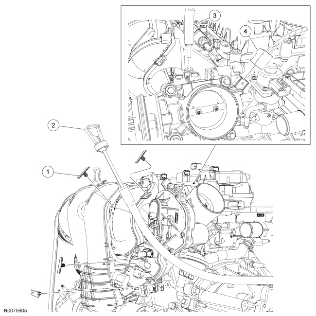
| Item | Part Number | Description |
|---|---|---|
| 1 | 13A506 | Wire harness pin-type retainer (part of 12C508) (4 required) |
| 2 | 7A020 | Transaxle fluid indicator |
| 3 | 19D848 | Power brake booster vacuum tube |
| 4 | 14A464 | Swirl control valve sensor electrical connector (part of 12C508) (if equipped) |
Intake Manifold (View 3 of 3)
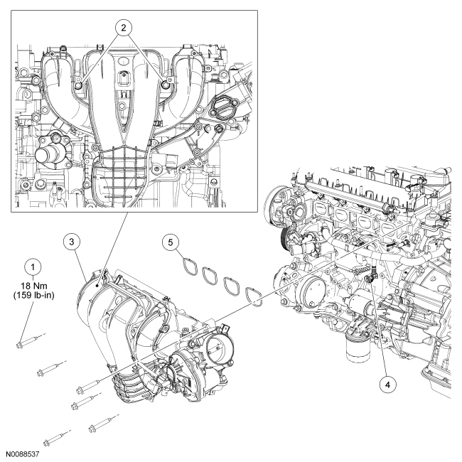
| Item | Part Number | Description |
|---|---|---|
| 1 | W500311 | Intake manifold bolt (6 required) |
| 2 | W500312 | Intake manifold bolts |
| 3 | 9424 | Intake manifold |
| 4 | 6758 | PCV hose |
| 5 | 9439 | Intake manifold gasket |
Removal
- With vehicle in NEUTRAL, position it on a hoist. For additional information, refer to Section 100-02.
- Remove the Air Cleaner (ACL) outlet pipe. For additional information, refer to Section 303-12.
- Remove the front impact severity sensor. For additional information, refer to Section 501-20B.
- Remove the transaxle fluid indicator.
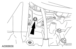
- Remove the lower intake manifold bolt.
- Remove the oil level indicator and tube. For additional information, refer to Oil Level Indicator and Tube in this section.
- Disconnect the Engine Oil Pressure (EOP) switch electrical connector and detach the wire harness retainer from the starter stud bolt.
- Disconnect the electronic throttle control electrical connector.
- Disconnect the fuel vapor return hose.
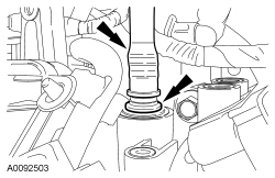
- Disconnect the power brake booster vacuum tube.
- Depress the quick release locking ring.
- Pull the vacuum tube out of the quick release fitting.
- Disconnect the Manifold Absolute Pressure (MAP) sensor electrical connector.
- Detach and disconnect the Knock Sensor (KS) electrical connector.
- If equipped, disconnect the swirl control valve solenoid electrical connector.
- If equipped, disconnect the swirl control valve sensor electrical connector.
- Detach all the wiring harness pin-type retainers from the intake manifold.
- NOTE:
The 2 intake manifold bolts differ in length from rest of the bolts and also retain a crash bracket to the intake manifold. The 2 bolts are equipped with an attachment feature that allows them to be loosened but remain attached to the intake manifold. Do not attempt to remove the 2 bolts or the crash bracket from the intake manifold.
Loosen the 2 intake manifold bolts.
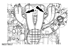
- Remove the 5 intake manifold bolts.
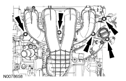
- Disconnect the PCV hose and remove the intake manifold.
Installation
- NOTICE: If the engine is repaired or replaced because of upper engine
failure, typically including valve or piston damage, check the intake manifold
for metal debris. If metal debris is found, install a new intake manifold. Failure
to follow these instructions can result in engine damage.
Inspect and install new intake manifold gaskets if necessary.
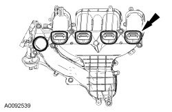
- Position the intake manifold and connect the PCV hose.
- Attach the KS to the intake manifold and connect the KS electrical connector.
- NOTE:
The 2 intake manifold bolts differ in length from rest of the bolts and also retain a crash bracket to the intake manifold. The 2 bolts are equipped with an attachment feature that allows them to be loosened but remain attached to the intake manifold. Do not attempt to remove the 2 bolts or the crash bracket from the intake manifold.
Install the intake manifold and hand-tighten the 2 intake manifold bolts.
- Install the 5 intake manifold mounting bolts.
- Tighten all 7 bolts to 18 Nm (159 lb-in).
- Attach all the wiring harness pin-type retainers to the intake manifold.
- If equipped, connect the swirl control valve sensor electrical connector.
- If equipped, connect the swirl control valve solenoid electrical connector.
- Connect the MAP sensor electrical connector.
- Connect the power brake booster vacuum tube.
- Push the vacuum tube into the quick release fitting.
- Connect the fuel vapor return hose.
- Connect the electronic throttle control electrical connector.
- Connect the EOP switch electrical connector and attach the wire harness retainer to the starter stud bolt.
- Install the oil level indicator and tube. For additional information, refer to Oil Level Indicator and Tube in this section.
- Install the lower intake manifold bolt.
- Tighten to 18 Nm (159 lb-in).
- Install the transaxle fluid indicator.
- Install the front impact severity sensor. For additional information, refer to Section 501-20B.
- Install the ACL outlet pipe. For additional information, refer to Section 303-12.
 Air Cleaner
Disconnect the Mass Air Flow (MAF) sensor electrical connector.
Loosen the clamp and separate the Air Cleaner (ACL) outlet pipe from the
ACL assembly.
To install, tighten to 3 Nm (2 ...
 Air Cleaner Outlet Pipe
Disconnect the crankcase ventilation tube and vacuum tube from the Air Cleaner
(ACL) outlet pipe.
Loosen the 2 ACL outlet pipe clamps.
Remove the ACL outlet pipe.
To insta ...
More about Ford Focus:
Ford Focus Towing a trailer
WARNINGS:
Do not exceed 100 km/h (62 mph).
The rear tyre pressures must be
increased by 0.2 bar (3 psi) above
specification. See Technical
specifications.
Do not exceed the maximum
vehicle and trailer weight stated on
the vehicle identification plate. See
Vehicle identification plate. ...
Nissan Frontier - Instrument Panel - Keys - Brake system
